
Designing Pneumatic Conveying Systems for Long Distances
Designing Pneumatic Conveying Systems for Long Distances
Pneumatic conveying systems are widely used to transport powders, pellets, granules and flakes across industrial plants. They are particularly valuable when material needs to travel long distances, cross different elevations, or follow complex routes where mechanical conveying systems become difficult to install.
Industries such as Polymer, Chemical, Petrochemical, Food and Mineral processing rely on pneumatic conveying for materials ranging from PP and PE pellets to PVC powder, chemical additives, catalyst powders, flour, sugar, silica and cement.
But long-distance pneumatic conveying presents a unique engineering challenge.
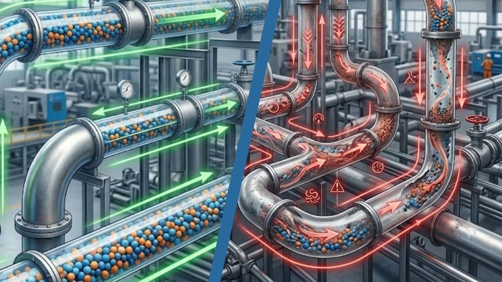
A conveying line that performs well over 100 meters may behave very differently when the distance increases to several hundred meters. Pressure drop accumulates, gas velocity changes, bends become more significant, and product degradation or pipeline instability can become major concerns.
The key is to understand that long-distance pneumatic conveying is not simply a longer version of a short conveying system. It requires system-level engineering.
Why Long-Distance Pneumatic Conveying Is Different
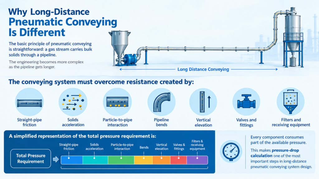
The basic principle of pneumatic conveying is straightforward: a gas stream carries bulk solids through a pipeline.
The engineering becomes more complex as the pipeline gets longer.
The conveying system must overcome resistance created by:
- Straight-pipe friction
- Solids acceleration
- Particle-to-pipe interaction
- Pipeline bends
- Vertical elevation
- Valves and fittings
- Filters and receiving equipment
ΔPTotal = ΔPPipe + ΔPSolids + ΔPBends + ΔPElevation + ΔPEquipment
Start With the Material, Not the Equipment
One of the most important principles in pneumatic conveying engineering is:
The material determines the conveying strategy
Different bulk solids behave differently inside a pipeline. Designing a system based only on throughput and distance can result in an unstable or inefficient system.
Important material properties include:
| Material Property | Engineering Significance |
|---|---|
| Bulk density | Determines solids loading and conveying behaviour |
| Particle size | Influences suspension and conveying velocity |
| Particle shape | Affects friction and particle-wall interaction |
| Moisture | Can influence cohesion and flowability |
| Friability | Determines risk of particle breakage |
| Cohesiveness | Important for powders and fine materials |
| Abrasiveness | Determines pipeline and bend wear |
| Electrostatic behavior | Can contribute to wall adhesion and dust |
| Temperature | Influences material and gas properties |
Examples across industries
Polymer: PP pellets, HDPE pellets, LLDPE pellets, PET chips, PVC powder and polymer regrind.
Chemical: Pigments, additives, resins, catalysts and specialty powders.
Petrochemical: Polyolefin pellets and polymer powders transported between silos, process units and packaging systems.
Food: Flour, sugar, starch, milk powder, spices and other dry ingredients.
Mineral: Silica, limestone, cement, fly ash and mineral powders.
The same pipeline design cannot automatically be applied to all these materials.
Selecting the Right Conveying Phase
Long-distance pneumatic conveying systems generally operate in either dilute phase or dense phase, depending on the material and application.
Dilute-phase conveying
In dilute phase, particles are suspended in a relatively high-velocity gas stream.
It is commonly used for:
- Powders
- Granules
- General-purpose material transfer
- Applications requiring relatively simple conveying arrangements
Dense-phase conveying
Dense phase operates at higher solids loading and generally lower gas velocity.
It can be particularly attractive for materials where product degradation is a concern.
For example, PP pellets, PE pellets and PET chips may benefit from controlled-velocity conveying where excessive particle impact needs to be minimized to avoid dust generation and angel hair formation.
| Parameter | Dilute Phase | Dense Phase |
|---|---|---|
| Gas velocity | Higher | Lower |
| Solids loading | Lower | Higher |
| Conveying pressure | Lower to moderate | Moderate to high |
| Product impact | Potentially higher | Generally lower |
| Control complexity | Relatively simple | Higher |
| Suitable materials | Powders, granules | Suitable pellets and sensitive solids |
There is no universal “best” conveying phase. The selection should be based on material behavior, capacity, distance and product-quality requirements.
Pipe Diameter: A Critical Design Decision
Pipeline diameter has a direct influence on conveying velocity.
The basic relationship is:
V = Q⁄A
where:
- V = gas velocity
- Q = volumetric gas flow
- A = pipeline cross-sectional area
- High pressure drop
- High gas velocity
- Increased product degradation
- Higher energy consumption
- Low conveying velocity
- Unstable solids transport
- Higher capital cost
- Larger blower or compressor gas volume requirement
Pressure Drop Is the Core Design Parameter
A long-distance pneumatic conveying system can be viewed as a pressure budget.
The available pressure from the blower, compressor or vacuum system must be sufficient to overcome the total system resistance.
The pressure budget should account for:
1. Gas friction
2. Solids friction
3. Acceleration losses
4. Bends
5. Vertical lifting
6. Valves and fittings
7. Feed equipment
8. Receiver and filter resistance
A useful engineering practice is to create a pressure profile along the entire pipeline.
Instead of looking only at the inlet and outlet pressure, the designer should understand how pressure changes along the route.
- Long horizontal sections
- Multiple bends
- Significant vertical elevation
- High throughput
- Dense-phase operation
Feeder Design Is Part of the Conveying System
A pneumatic pipeline cannot perform reliably if the material is fed into it inconsistently.
Depending on the application, systems may use:
- Rotary airlocks
- Screw feeders
- Pressure vessels or Blow tanks
- Venturi feeders
The feeder must provide controlled solids flow while maintaining the required pressure boundary.
Air leakage through the feeding system can also affect the conveying balance.
For long-distance systems, unstable feeding can lead to:
- Fluctuating pressure
- Variable throughput
- Increased solids loading
- Pipeline instability
- Plugging
Therefore, feeder selection and pipeline design should be considered together.
Bends Are More Than Just Direction Changes
Bends are among the most critical components in a pneumatic conveying pipeline.
When particles change direction, they interact with the bend wall. At high velocities, this interaction can become severe.
This can result in:
- Particle impact
- Fines generation
- Product degradation
- Pipeline wear
- Increased pressure drop
For polymer pellets and PET chips, bend design can directly influence product quality.
Depending on the application, engineers may consider:
- Long-radius bends
- Special-radius bends
- Pellet-cushion bends
- Streamer-guard bends
- Wear-resistant bends
The right bend should be selected based on particle properties, conveying velocity, solids loading and expected service life.
Receiver and Filtration Should Not Be an Afterthought
At the end of a long conveying line, the receiving system must separate the solids from the conveying gas effectively.
Depending on the application, this may include:
- Cyclones
- Bag filters
- Cartridge filters
- Bin vents
- Central dust collection systems
Filter differential pressure should be included in the overall system pressure calculation.
As filters load with dust, resistance increases.
Therefore, the system should be evaluated under both:
Engineering Workflow for Long-Distance Pneumatic Conveying
| Step | Engineering Activity |
|---|---|
| 1 | Characterize the material |
| 2 | Define required throughput |
| 3 | Establish horizontal and vertical pipeline length |
| 4 | Select pressure or vacuum conveying |
| 5 | Evaluate dilute or dense phase |
| 6 | Determine conveying velocity |
| 7 | Select pipeline diameter |
| 8 | Calculate total pressure drop |
| 9 | Evaluate bends and fittings |
| 10 | Select feeder and gas-moving equipment |
| 11 | Design receiver and filtration |
| 12 | Develop instrumentation and controls |
| 13 | Validate critical parameters through testing |
| 14 | Optimize the complete system |
Conclusion:
Designing pneumatic conveying systems for long distances requires a different mindset from conventional material-transfer design.
The objective is not simply to move material over a longer pipeline. The objective is to create a system where material characteristics, conveying phase, velocity, solids loading, pipeline diameter, bends, elevation, pressure drop and energy consumption work together.
For Polymer and Petrochemical industries, this may mean transporting PP pellets, PE pellets, PET chips or polymer powders while controlling degradation and fines. In the Chemical industry, powders, additives and granules may require careful control of cohesion, dust and flowability. If the powder has high risks of potential explosion, then conveying must be done with an inert gas in a closed loop conveying configuration. Food industries may need gentle and hygienic conveying of flour, sugar, starch and milk powder. Mineral industries may prioritize abrasion resistance, dust control and stable high-solids conveying for materials such as silica, limestone and cement.
The most effective long-distance pneumatic conveying systems are therefore built around a simple engineering philosophy:
Design the complete conveying system – not just the pipeline
When pressure drop is understood, velocity is optimized, pipeline geometry is engineered, and material behavior is validated, long-distance pneumatic conveying can provide reliable throughput, controlled product quality, lower operating risk and improved energy efficiency across demanding industrial applications.