Indpro Logo

Indpro
Typically replies within an hour

Indpro
"Hello!👋

How can I help you today with your bulk material handling needs?"
×
Chat with Us

Designing Pneumatic Conveying Systems for Long Distances

Designing Pneumatic Conveying Systems for Long Distances

Pneumatic conveying systems are widely used to transport powders, pellets, granules and flakes across industrial plants. They are particularly valuable when material needs to travel long distances, cross different elevations, or follow complex routes where mechanical conveying systems become difficult to install.

Industries such as Polymer, Chemical, Petrochemical, Food and Mineral processing rely on pneumatic conveying for materials ranging from PP and PE pellets to PVC powder, chemical additives, catalyst powders, flour, sugar, silica and cement.

But long-distance pneumatic conveying presents a unique engineering challenge.

A conveying line that performs well over 100 meters may behave very differently when the distance increases to several hundred meters. Pressure drop accumulates, gas velocity changes, bends become more significant, and product degradation or pipeline instability can become major concerns.

The key is to understand that long-distance pneumatic conveying is not simply a longer version of a short conveying system. It requires system-level engineering.


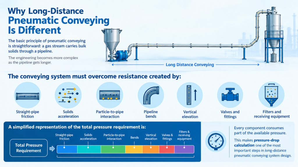
Why Long-Distance Pneumatic Conveying Is Different

The basic principle of pneumatic conveying is straightforward: a gas stream carries bulk solids through a pipeline.

The engineering becomes more complex as the pipeline gets longer.

The conveying system must overcome resistance created by:

  • Straight-pipe friction 
  • Solids acceleration 
  • Particle-to-pipe interaction 
  • Pipeline bends 
  • Vertical elevation 
  • Valves and fittings 
  • Filters and receiving equipment 
A simplified representation of the total pressure requirement is:

ΔPTotal = ΔPPipe + ΔPSolids + ΔPBends + ΔPElevation + ΔPEquipment

Every component consumes part of the available pressure.
This makes pressure-drop calculation one of the most important steps in long-distance pneumatic conveying system design.


Start With the Material, Not the Equipment

One of the most important principles in pneumatic conveying engineering is:

The material determines the conveying strategy

Different bulk solids behave differently inside a pipeline. Designing a system based only on throughput and distance can result in an unstable or inefficient system.

Important material properties include:

Material PropertyEngineering Significance
Bulk densityDetermines solids loading and conveying behaviour
Particle sizeInfluences suspension and conveying velocity
Particle shapeAffects friction and particle-wall interaction
MoistureCan influence cohesion and flowability
FriabilityDetermines risk of particle breakage
CohesivenessImportant for powders and fine materials
AbrasivenessDetermines pipeline and bend wear
Electrostatic behaviorCan contribute to wall adhesion and dust
TemperatureInfluences material and gas properties

Examples across industries

Polymer: PP pellets, HDPE pellets, LLDPE pellets, PET chips, PVC powder and polymer regrind.

Chemical: Pigments, additives, resins, catalysts and specialty powders.

Petrochemical: Polyolefin pellets and polymer powders transported between silos, process units and packaging systems.

Food: Flour, sugar, starch, milk powder, spices and other dry ingredients.

Mineral: Silica, limestone, cement, fly ash and mineral powders.

The same pipeline design cannot automatically be applied to all these materials.


Selecting the Right Conveying Phase

Long-distance pneumatic conveying systems generally operate in either dilute phase or dense phase, depending on the material and application.

Dilute-phase conveying

In dilute phase, particles are suspended in a relatively high-velocity gas stream.

It is commonly used for:

  • Powders 
  • Granules 
  • General-purpose material transfer 
  • Applications requiring relatively simple conveying arrangements

Dense-phase conveying

Dense phase operates at higher solids loading and generally lower gas velocity.

It can be particularly attractive for materials where product degradation is a concern.

For example, PP pellets, PE pellets and PET chips may benefit from controlled-velocity conveying where excessive particle impact needs to be minimized to avoid dust generation and angel hair formation.

ParameterDilute PhaseDense Phase
Gas velocityHigherLower
Solids loadingLowerHigher
Conveying pressureLower to moderateModerate to high
Product impactPotentially higherGenerally lower
Control complexityRelatively simpleHigher
Suitable materialsPowders, granulesSuitable pellets and sensitive solids

There is no universal “best” conveying phase. The selection should be based on material behavior, capacity, distance and product-quality requirements.


Pipe Diameter: A Critical Design Decision

Pipeline diameter has a direct influence on conveying velocity.

The basic relationship is:

V = Q⁄A

where:

  • V = gas velocity 
  • Q = volumetric gas flow 
  • A = pipeline cross-sectional area 
As pipe diameter increases, the cross-sectional area increases significantly.
 
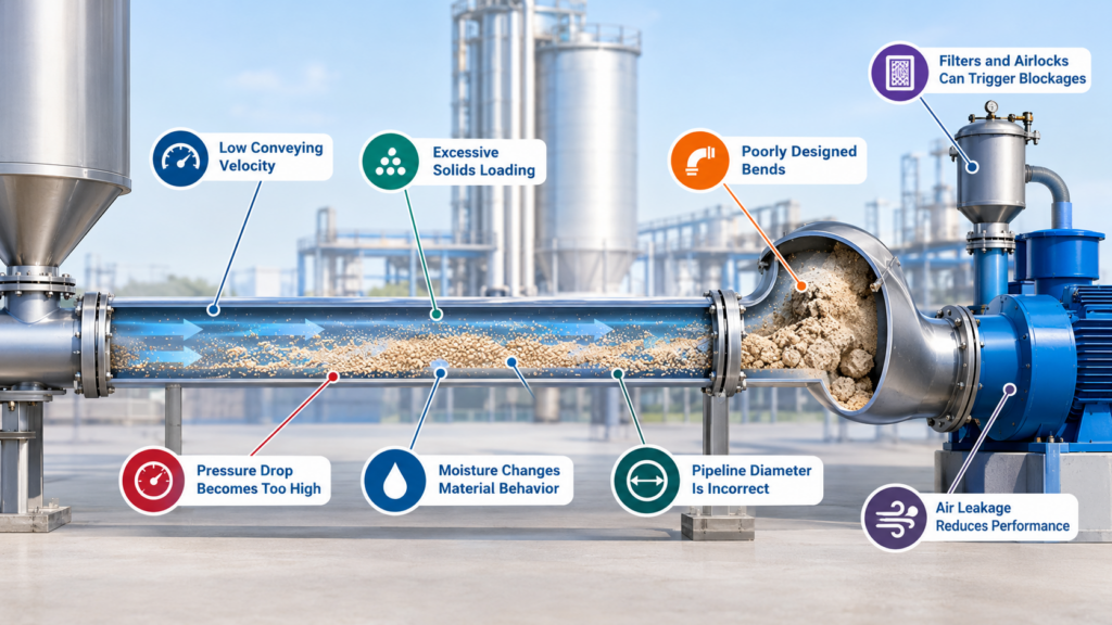
A smaller pipeline can produce higher gas velocity and potentially higher-pressure drop. An excessively large pipeline, on the other hand, may reduce velocity to a level where stable conveying becomes difficult.
 
Undersized pipeline

Possible consequences include:
  • High pressure drop 
  • High gas velocity 
  • Increased product degradation 
  • Higher energy consumption
 Oversized pipeline
 
Possible consequences include:
  • Low conveying velocity 
  • Unstable solids transport 
  • Higher capital cost 
  • Larger blower or compressor gas volume requirement
The objective is not to select the largest or smallest possible pipe.
 
It is to select the optimum diameter for stable conveying, pressure drop, energy consumption, and product quality. 


Pressure Drop Is the Core Design Parameter

A long-distance pneumatic conveying system can be viewed as a pressure budget.

The available pressure from the blower, compressor or vacuum system must be sufficient to overcome the total system resistance.

The pressure budget should account for:

1. Gas friction 

2. Solids friction 

3. Acceleration losses 

4. Bends 

5. Vertical lifting 

6. Valves and fittings 

7. Feed equipment 

8. Receiver and filter resistance 

A useful engineering practice is to create a pressure profile along the entire pipeline.

Instead of looking only at the inlet and outlet pressure, the designer should understand how pressure changes along the route.

This becomes especially important for pipelines with: 

  • Long horizontal sections 
  • Multiple bends 
  • Significant vertical elevation 
  • High throughput 
  • Dense-phase operation 


Feeder Design Is Part of the Conveying System

A pneumatic pipeline cannot perform reliably if the material is fed into it inconsistently.

Depending on the application, systems may use:

  • Rotary airlocks 
  • Screw feeders 
  • Pressure vessels or Blow tanks 
  • Venturi feeders  

The feeder must provide controlled solids flow while maintaining the required pressure boundary.

Air leakage through the feeding system can also affect the conveying balance.

For long-distance systems, unstable feeding can lead to:

  • Fluctuating pressure 
  • Variable throughput 
  • Increased solids loading 
  • Pipeline instability 
  • Plugging 

Therefore, feeder selection and pipeline design should be considered together.


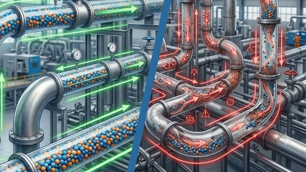
Bends Are More Than Just Direction Changes

Bends are among the most critical components in a pneumatic conveying pipeline.

When particles change direction, they interact with the bend wall. At high velocities, this interaction can become severe.

This can result in:

  • Particle impact 
  • Fines generation 
  • Product degradation 
  • Pipeline wear 
  • Increased pressure drop  

For polymer pellets and PET chips, bend design can directly influence product quality.

Depending on the application, engineers may consider:

  • Long-radius bends 
  • Special-radius bends 
  • Pellet-cushion bends 
  • Streamer-guard bends 
  • Wear-resistant bends 

The right bend should be selected based on particle properties, conveying velocity, solids loading and expected service life.


Receiver and Filtration Should Not Be an Afterthought

At the end of a long conveying line, the receiving system must separate the solids from the conveying gas effectively.

Depending on the application, this may include:

  • Cyclones 
  • Bag filters 
  • Cartridge filters 
  • Bin vents 
  • Central dust collection systems 

Filter differential pressure should be included in the overall system pressure calculation.

As filters load with dust, resistance increases.

Therefore, the system should be evaluated under both:

 Clean-filter condition → Dirty-filter condition
 
This ensures that the blower or compressor is not selected only for an ideal laboratory condition.


Engineering Workflow for Long-Distance Pneumatic Conveying

StepEngineering Activity
1Characterize the material
2Define required throughput
3Establish horizontal and vertical pipeline length
4Select pressure or vacuum conveying
5Evaluate dilute or dense phase
6Determine conveying velocity
7Select pipeline diameter
8Calculate total pressure drop
9Evaluate bends and fittings
10Select feeder and gas-moving equipment
11Design receiver and filtration
12Develop instrumentation and controls
13Validate critical parameters through testing
14Optimize the complete system


Conclusion:


Designing pneumatic conveying systems for long distances requires a different mindset from conventional material-transfer design.

The objective is not simply to move material over a longer pipeline. The objective is to create a system where material characteristics, conveying phase, velocity, solids loading, pipeline diameter, bends, elevation, pressure drop and energy consumption work together.

For Polymer and Petrochemical industries, this may mean transporting PP pellets, PE pellets, PET chips or polymer powders while controlling degradation and fines. In the Chemical industry, powders, additives and granules may require careful control of cohesion, dust and flowability. If the powder has high risks of potential explosion, then conveying must be done with an inert gas in a closed loop conveying configuration. Food industries may need gentle and hygienic conveying of flour, sugar, starch and milk powder. Mineral industries may prioritize abrasion resistance, dust control and stable high-solids conveying for materials such as silica, limestone and cement.

The most effective long-distance pneumatic conveying systems are therefore built around a simple engineering philosophy:

Design the complete conveying system – not just the pipeline

When pressure drop is understood, velocity is optimized, pipeline geometry is engineered, and material behavior is validated, long-distance pneumatic conveying can provide reliable throughput, controlled product quality, lower operating risk and improved energy efficiency across demanding industrial applications.

The Hidden Cost of Poor Material Feeding in Pneumatic Conveying

The Hidden Cost of Poor Material Feeding in Pneumatic Conveying

In pneumatic conveying, the most expensive problems are often not created in the pipeline: They begin upstream.

A conveying system can be correctly sized, carefully engineered, and equipped with an efficient blower – yet still underperform because material is entering the conveying line inconsistently. When the feed device floods, starves, surges, aerates, compacts, or simply fails to maintain a stable solids-to-air ratio, the entire system is forced to operate outside its intended design envelope.

The result is a deceptively familiar pattern: higher energy consumption, unstable throughput, excessive wear, filter loading, product degradation, frequent blockages, and operators constantly adjusting equipment to compensate. 

The mistake is to treat feeding as a mechanical handoff.

In reality, the feeder is the point where the material process becomes a conveying process.

That makes feeding one of the most consequential – and frequently underestimated – variables in pneumatic conveying. 


The Feeder Is Not Just a Valve Between Processes

A pneumatic conveying system has two fundamentally different phases.

Before the material enters the conveying line, it behaves according to gravity, bulk-solid mechanics, hopper geometry, moisture, particle size distribution, cohesiveness, and other material properties.

Once it enters the pipeline, its behavior is governed by airflow, particle velocity, pressure, suspension, acceleration, friction, and phase regime.

The feeder sits at the boundary between these worlds.

Its job is therefore more sophisticated than simply delivering material at a specified rate. It must introduce solids into an air stream at a controlled and repeatable rate while maintaining the pressure boundary of the conveying system.

When this interface is poorly controlled, disturbances propagate downstream.

A small variation in feed rate can change the solids loading ratio. This alters pressure drop. Pressure changes affect conveying velocity. Velocity changes affect particle acceleration and impact. Those changes can influence separation efficiency, filter loading, and even the operating point of the blower.

What looks like a feeding problem can consequently become a system-wide performance problem. 


The First Hidden Cost: Energy

Energy is usually the easiest cost to identify, but it is rarely the first symptom operators notice.

Consider a system designed to transport material at a relatively stable solids loading. If feeding becomes intermittent, the conveying line alternates between heavily loaded and lightly loaded conditions.

During the heavily loaded portion, pressure drop rises.

Operators may respond by increasing blower speed or opening an air valve to prevent plugging. But when the material feed subsequently falls away, the system can be left moving considerably more air than necessary.

The plant then pays twice:
  • More air is compressed or moved than the process requires.
  • Higher conveying velocities can increase pressure loss and material acceleration.

This is why simply comparing a blower’s rated efficiency with its actual electrical consumption can be misleading.

The real question is not “How efficient is the blower?” but “How efficiently is the entire conveying system using the air?”

A well-controlled feeder can be an energy-management device.

It keeps the solids loading closer to the intended operating point, reducing the need for excessive air as a safety margin.


The Second Hidden Cost: Throughput You Never Recover

Poor feeding does not necessarily announce itself as “low capacity.”

More often, production teams experience it as variability.

One shift achieves the target rate. Another struggles. A line runs well in the morning but becomes unreliable after several hours. Operators periodically increase airflow, reduce feed rate, clear a restriction, or restart the system.

The annualized production loss can be substantial.

Imagine a conveying line nominally capable of 10 tones per hour. If unstable feeding causes the process to operate at an effective average of 8.5 tones per hour, the lost capacity is not merely the difference between two numbers on a specification sheet.

It becomes:

lost production × operating hours × contribution margin.

That can dwarf the apparent cost of the feeder itself.

This is one reason feeder selection should be based on total conveying economics, rather than purchase price or nominal feed capacity.


The Third Hidden Cost: Wear Caused by Excessive Velocity

A common response to unreliable feeding is to increase conveying air.

It is understandable. More air creates a larger safety margin against settling and blockage.

But that safety margin has a price.

Higher gas velocity generally means greater particle velocity. Depending on the material and conveying regime, that can increase:

  • Elbow erosion
  • Pipeline wear
  • Particle impact
  • Product attrition
  • Dust generation
  • Filter loading
  • Equipment vibration
The irony is important: 

A feeder that cannot deliver material consistently may force the conveying system to operate at velocities that shorten the life of the conveying system itself.

In abrasive applications, the consequences can be especially severe. A modest increase in velocity can have an outsized impact on wear because erosion is strongly influenced by particle velocity, impact angle, particle characteristics, and equipment geometry.

The result is a classic hidden cost: the feeder appears inexpensive while downstream components quietly consume maintenance budgets. 


The Fourth Hidden Cost: Product Quality

Engineers often evaluate conveying performance in terms of tones per hour and pressure drop.

Product manufacturers have another metric:

What happened to the product while it was being conveyed?

Fragile granules, crystals, pellets, agglomerates, flakes, and other sensitive materials can suffer degradation when feeding and conveying conditions are poorly controlled.

Unstable feeding can create periods of high solids concentration followed by high-velocity, low-solids transport. Repeated acceleration and impact can increase attrition and fines generation.

That can affect:

  • Particle-size distribution
  • Bulk density
  • Appearance
  • Flowability
  • Dissolution characteristics
  • Downstream processing
  • Yield
In food, pharmaceutical, chemical, and specialty-material applications, the cost of degradation can be far greater than the cost of conveying energy.
 
A feeder should therefore be evaluated not only by how much material it can move, but by how gently and consistently it introduces that material into the process.


Impact Across Key Processing Industries

Industry Material Examples Impact of Poor Feeding & Velocity Surges
Polymers Polyethylene (LLDPE/HDPE), Polypropylene (PP) Pellets, PVC Resins, PET Chips, Polystyrene High friction and impact velocity cause localized frictional melting. This generates “angel hair” or streamers, clogging downstream receiver screens and contaminating batches.
Food Industry Spray-Dried Milk Powder, Infant Formula, Instant Coffee Granules, Extruded Pet Food, Granulated Sugar, Wheat Flour High impact energy breaks fragile agglomerates (Rittinger’s Law), converting premium instantized product into fines and dust. This creates caking issues and packaging weight errors.
Chemicals Titanium Dioxide TiO2, Soda Ash, Carbon Black, Hydrated Lime, Organic Pigments, Catalyst Pellets Fine cohesive powders tend to pack under pressure surges. Surging causes pipe wall coating, line plugs, and high pipe elbow wear from abrasive fines.


The Solids-To-Air Ratio Is a Strategic Variable

One of the most useful ways to think about feeding is through the relationship between solids flow and gas flow. The conveying system is not simply moving “material through a pipe.” It is creating a controlled interaction between solids and gas.

If solids feed varies substantially while airflow remains fixed, the solids loading ratio varies.

If airflow is adjusted aggressively to compensate, conveying velocity varies.

Either way, the system is moving away from a stable operating point.

This is why sophisticated conveying systems increasingly focus on control of the process, rather than simply selection of individual components.

Stable feeding creates a more predictable solids loading.

Predictable loading enables more disciplined air management.

Better air management reduces unnecessary velocity.

Lower and more controlled velocity can reduce energy consumption, wear, and product damage.

In other words: Feeding stability is a multiplier.

It improves several downstream variables simultaneously.


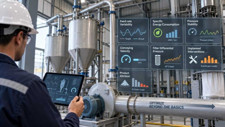
What Leading Plants Are Measuring Differently

What Leading Plants Are Measuring Differently

The most mature pneumatic conveying operations are moving beyond traditional KPIs such as:.

  • Motor current
  • Blower pressure
  • Tones per hour
  • Number of blockages

These remain useful, but they do not necessarily identify the root cause.

More revealing indicators include:

Feed-rate variability: How far does actual material delivery deviate from the target?

Specific energy consumption: How much electrical energy is consumed per ton conveyed?

Pressure stability: How much does conveying pressure fluctuate during steady-state operation?

Conveying velocity: Is the system operating faster than necessary?

Filter differential pressure: Is unstable conveying increasing dust loading?

Unplanned interventions: How frequently do operators need to adjust or reset the system?

Product attrition: How much usable product is converted into fines or otherwise lost?

Together, these measurements reveal whether the system is genuinely optimized – or simply being kept operational. 


Conclusion:


Poor material feeding is rarely recorded as a single line item on a plant’s income statement.

Instead, its cost is scattered across electricity, maintenance, spare parts, lost production, labor, quality deviations, filter replacements, product waste, and operator intervention.

That fragmentation makes the problem easy to underestimate. But the physics do not care where the cost appears in the accounting system.

An unstable feed creates an unstable conveying process and an unstable conveying process forces every downstream component to compensate.

 The strategic implication is straightforward:

Pipeline Layout Is an Engineering Decision, not a Drafting Exercise


The feeder is not merely the beginning of the pipeline

It is the control point that determines how efficiently the entire pneumatic conveying system can operate.


When material feeding is stable, predictable, and matched to the conveying regime, the benefits compound: lower energy consumption, steadier throughput, less wear, fewer blockages, better product integrity, reduced operator intervention, and more predictable production.

That is why the hidden cost of poor feeding is ultimately much larger than the feeder itself: It is the cost of making the rest of the plant compensate for an unstable beginning.


How Pipeline Layout Affects Conveying Performance

How Pipeline Layout Affects Conveying Performance

When designing a pneumatic conveying system, most discussions focus on conveying capacity, blower selection, pipe diameter, or conveying mode. However, one of the most influential factors is often overlooked – the pipeline layout itself.

A pipeline is not merely a connection between a material source and a destination. It is an active component that directly affects pressure drop, conveying velocity, energy consumption, material degradation, equipment wear, and overall system reliability. 

Two conveying systems handling the same material at the same capacity can perform very differently simply because their pipeline layouts are different. A system with excessive bends, abrupt directional changes, unnecessary vertical lifts, or poorly selected pipe diameters may require more energy, generate more fines, and experience frequent operational issues.

This is particularly important in industries handling bulk solids such as:

  • Polymers – PP, PE, PET, PVC, ABS, Engineering Plastics
  • Chemicals – Calcium Carbonate, Titanium Dioxide, Pigments, Detergent Powders, Additives
  • Food & Beverage – Flour, Sugar, Starch, Milk Powder, Cocoa, Protein Powders
  • Minerals – Cement, Fly Ash, Lime, Silica, Alumina, Sand
Understanding how pipeline layout influences conveying behavior allows engineers to design systems that are not only capable of conveying material, but capable of doing so efficiently and reliably over the long term.


How Pipeline Layout Affects Conveying Performance

1. Pipeline Length

Every meter of pipeline creates resistance to flow.

As conveying air and solids travel through the pipeline, friction between the gas, particles, and pipe wall causes pressure loss. The longer the pipeline, the greater the pressure drop the conveying system must overcome.

While longer pipelines naturally require more conveying energy, total pipeline length alone does not determine system performance. The overall layout must also consider bends, elevation changes, and fittings.

The most effective design is not necessarily the shortest physical route, but the route that minimizes overall conveying resistance by strategically placing bends.

2. Pipe Diameter

Pipe diameter directly influences conveying velocity.

For a given airflow rate:

  • Smaller pipe diameter increases velocity.
  • Larger pipe diameter decreases velocity.
Excessively high velocities can result in:
 
  • Particle degradation
  • Product attrition
  • Angel hair formation in polymer pellets
  • Increased pipe wear
  • Higher energy consumption
Conversely, excessively low velocities can lead to:
 
  • Material settling
  • Pipeline blockages
  • Segregation
  • Unstable conveying conditions
The optimum pipe diameter is therefore one that maintains material movement within the required conveying velocity range while minimizing pressure loss.
 

3. Bends and Directional Changes

Among all pipeline components, bends often have the greatest influence on conveying performance.

Unlike air, solid particles possess momentum. When particles encounter a bend, they naturally attempt to continue moving in their original direction. As a result, they impact the pipe wall before changing direction.

This creates:

  • Additional pressure drop
  • Particle velocity reduction
  • Material degradation
  • Pipe wear
  • Increased energy requirements
After exiting a bend, particles must be re-accelerated by the conveying air, which consumes additional energy.
A pipeline with numerous bends may therefore exhibit significantly higher resistance than a longer pipeline with fewer directional changes.
 
For this reason, bend selection and placement are critical elements of conveying system design.
 

4. Elevation Changes

Vertical conveying introduces an additional challenge: gravity.

When material is conveyed upward, the conveying gas must provide sufficient energy not only to overcome friction but also to lift the material.

As vertical height increases:

  • Pressure requirements increase.
  • Airflow requirements may increase.
  • System operating margins become narrower.
Consequently, a pipeline containing multiple vertical risers often requires greater conveying pressure than a similar horizontal pipeline.
 
Pipeline routing should therefore minimize unnecessary elevation changes wherever practical.


Engineering Laws Governing Pipeline Layout

The relationship between pipeline geometry and conveying performance is governed by several well-established engineering principles.
Engineering Law / Principle Relationship Significance in Pneumatic Conveying
Continuity Equation Q = A × V Pipe diameter directly influences conveying velocity.
Bernoulli Principle Pressure, velocity and elevation are interrelated. Elevation changes affect pressure requirements.
Darcy-Weisbach Equation Pressure loss increases with length and velocity. Longer pipelines create higher pressure drops.
Momentum Conservation Changing particle direction requires force. Bends introduce momentum loss and pressure drop.
Kinetic Energy Principle KE = ½mv² Impact forces increase rapidly as velocity increases.
Reynolds Number Determines flow characteristics. Influences gas-flow behavior and friction losses.
Terminal Velocity Principle Each particle has a minimum suspension velocity. Velocity must remain above the settling limit.
Energy Conservation Input energy must overcome all system losses. Pipeline layout directly influences power consumption.
Wear-Velocity Relationship Wear increases with particle impact velocity. Critical for abrasive minerals and high-capacity systems.


Effect of Pipeline Layout on Different Materials

Industry Typical Materials Key Material Characteristics Effect of Pipeline Layout Consequences of Poor Layout
Polymer PP, PE, HDPE, LLDPE, PET Chips, PVC, ABS Relatively free-flowing; pellets/chips can be sensitive to impact and friction Excessive bends and high velocities increase particle impact and can generate fines Pellet breakage, fines generation, angel hair, dust, product degradation
Chemical CaCO3, TiO2, Carbon Black, Pigments, Detergent Powders, Additives Wide range of particle sizes; some powders are cohesive, fine or hygroscopic Poor routing can increase pressure drop, material accumulation and segregation Blockage, segregation, dust generation, inconsistent product quality
Food & Beverage Flour, Sugar, Starch, Milk Powder, Cocoa, Protein Powders Often fine, fragile and sensitive to contamination and moisture Poor layouts can create retention zones and excessive particle impacts Product degradation, contamination, material retention, cleaning difficulties
Minerals Cement, Fly Ash, Silica, Alumina, Lime, Sand Often dense and highly abrasive Bends and high-velocity zones experience significant particle impact and erosion Pipe erosion, frequent maintenance, pressure-drop increase, unplanned shutdowns
Specialty / Fine Powders Battery powders, catalysts, pharmaceutical powders, specialty additives Very fine, lightweight, cohesive or sensitive to contamination Layout strongly affects dispersion, deposition, dust generation and product integrity Dusting, deposition, segregation, contamination, unstable conveying


Bend and Routing Optimization

Because bends are often the largest contributors to pressure loss and wear, their design deserves special attention. 

Ø   Minimize Bend Count

Every bend introduces additional resistance.

A route with fewer bends will generally provide:

  • Lower pressure drop
  • Reduced energy consumption
  • Less product degradation
  • Improved system reliability
 

Ø   Use Appropriate Bend Geometry

Long-radius bends typically provide smoother directional changes than short-radius bends.

Benefits include:

  • Lower impact forces
  • Reduced pressure loss
  • Lower wear rates
  • Improved product quality
The optimum bend design should always be selected based on the material characteristics and conveying velocity.
 

Ø   Avoid Clustering Bends

When multiple bends are installed close together, particles may not have sufficient distance to stabilize before entering the next bend.

This can result in:

  • Higher pressure losses
  • Increased turbulence
  • Greater particle degradation
  • Choking potential
Where possible, provide adequate straight sections between bends.
 

Ø   Consider Future Expansion

Pipeline layouts should accommodate future plant requirements.

Designing for future capacity increases can help avoid costly modifications later.

Key considerations include:

  • Spare conveying capacity
  • Additional destination points
  • Future production increases
  • Equipment accessibility
A well-planned layout provides both operational efficiency and long-term flexibility.


Pipeline Layout Optimization Checklist

The following checklist can help engineers evaluate whether a pipeline layout is optimized for performance:  
Parameter Engineering Consideration
Pipeline Length Eliminate unnecessary routing wherever possible.
Pipe Diameter Maintain suitable conveying velocity.
Number of Bends Minimize directional changes.
Bend Radius Use appropriate long-radius geometry where feasible.
Vertical Lifts Reduce unnecessary elevation changes.
Velocity Profile Ensure velocity remains within the material’s operating window.
Material Characteristics Consider particle size, density, abrasiveness and fragility.
Pressure Drop Calculate total system resistance, not just pipe length.
Wear Zones Identify high-impact areas and provide protection if required.
Product Quality Evaluate risk of degradation, dust generation and segregation.
Maintenance Access Ensure inspection and replacement points are accessible.
Future Capacity Allow flexibility for plant expansion.
Pipeline Length
Eliminate unnecessary routing wherever possible.
Pipe Diameter
Maintain suitable conveying velocity.
Number of Bends
Minimize directional changes.
Bend Radius
Use appropriate long-radius geometry where feasible.
Vertical Lifts
Reduce unnecessary elevation changes.
Velocity Profile
Ensure velocity remains within the material’s operating window.
Material Characteristics
Consider particle size, density, abrasiveness and fragility.
Pressure Drop
Calculate total system resistance, not just pipe length.
Wear Zones
Identify high-impact areas and provide protection if required.
Product Quality
Evaluate risk of degradation, dust generation and segregation.
Maintenance Access
Ensure inspection and replacement points are accessible.
Future Capacity
Allow flexibility for plant expansion.


Conclusion:


Pipeline layout has a profound influence on pneumatic conveying performance. It affects how efficiently energy is transferred, how materials behave within the pipeline, and ultimately how reliably the entire conveying system operates.

Length, diameter, bends, and elevation changes all contribute to the pressure and velocity profile experienced by the material. When these factors are properly engineered, conveying systems achieve higher capacities, lower operating costs, reduced maintenance, and improved product quality.

Whether conveying polymer pellets, chemical powders, food ingredients, or abrasive minerals, successful pneumatic conveying begins with understanding that the pipeline is not simply a route – it is a critical process component.

The most effective conveying systems are therefore not designed around the shortest path between two points, but around the path that best manages pressure, velocity, material integrity, and energy consumption.

Pipeline Layout Is an Engineering Decision, not a Drafting Exercise

Handling Ultra-Light Particle Powders in Pneumatic Conveying System

Handling Ultra-Light Particle Powders in Pneumatic Conveying System

Pneumatic conveying is widely used for transporting powders because it provides a closed, flexible and hygienic method of material transfer. However, when the material becomes extremely fine, lightweight and cohesive, conventional conveying approaches can become difficult to control.

Ultra-light particle powders such as silica, carbon black, titanium dioxide, pigments, specialty chemicals, battery materials, pharmaceutical powders and other micron-sized materials behave very differently from conventional pellets and granular solids.

The fundamental reason is simple: as particle size and mass decrease, the influence of the conveying gas becomes much stronger.

An ultra-fine particle has very low inertia and a high surface-area-to-mass ratio. It can therefore respond rapidly to changes in gas velocity, pressure and flow direction. At the same time, forces such as cohesion, electrostatics and moisture-induced adhesion can make the same powder difficult to feed or discharge.

This creates an important engineering paradox:

A powder can be easy to suspend in air, but difficult to feed consistently.

Therefore, the objective of pneumatic conveying should not simply be to “move the powder.”

The objective is to establish a stable gas – solid operating window in which the powder can be fed, conveyed and separated reliably without excessive energy consumption, degradation, segregation or dust generation.


Why Conventional Conveying Approaches Fail

A common approach to an unstable conveying system is to increase the conveying-air velocity.

While this may temporarily prevent material deposition, it can create other problems:

  • Higher pressure drop
  • Increased blower/compressor power
  • Excessive turbulence
  • Greater dust loading
  • Higher filter differential pressure
  • Increased electrostatic charging
  • Increased particle-wall interaction

The opposite problem can occur when velocity is too low.

Conveying conditionPotential consequence
Velocity too lowParticle settling, deposition and blockage
Velocity too highExcessive pressure drop, energy consumption and dust loading
Solids loading too lowHigh air consumption and inefficient transport
Solids loading too highUnstable conveying or excessive pressure requirement
Unstable feedingFluctuating pressure and conveying performance
Poor gas–solid separationPowder loss and excessive filter loading

This demonstrates why “more air” is not a universal solution.

The conveying system must be designed around the properties of the powder and operated within an appropriate range of velocity, pressure and solids loading.

The central engineering question therefore becomes:

What combination of air velocity, solids loading, pressure and powder-feed conditions will produce stable transport?


Key Engineering Laws

Engineering principles are essential for understanding the behaviour of ultra-light particle powders in pneumatic conveying

Engineering Law
/ Principle
Simple
 Relationship

What It Means in Pneumatic Conveying

Newton’s Second LawF = m aThe conveying gas applies aerodynamic force to the particles.
Because ultra-light particles have very low mass, they accelerate
and respond rapidly to changes in the gas stream.
Continuity EquationQ = A VFor a given airflow, reducing pipe diameter increases gas velocity,
while increasing diameter reduces velocity. Pipeline diameter
therefore directly influences conveying stability.
Drag / Stokes PrincipleF = 6π η r vVery fine particles are strongly influenced by the conveying gas
and can closely follow changes in gas direction and velocity.
Solids Loading Ratioφ = ṁs / ṁgDefines the relationship between powder flow and conveying-gas flow.
It is fundamental to selecting and controlling the conveying regime.
Kinetic Energy PrincipleKE = ½ m v2Particle kinetic energy increases with the square of velocity.
Unnecessarily high conveying velocity can therefore increase
energy consumption and particle interaction.

These principles lead to one important conclusion: Conveying velocity should be controlled – not maximized.


Critical Design Parameters

Successful ultra-light particle powder conveying depends on several interconnected material and process parameters. 

ParameterWhy It MattersDesign Consideration
Particle sizeDetermines aerodynamic responseVery fine particles follow the gas more closely
Particle densityInfluences particle inertiaLower inertia increases sensitivity to gas flow
Bulk densityDetermines volumetric powder flowImportant for feeder and pipeline sizing
CohesionAffects powder flowabilityMay cause bridging, rat-holing and unstable feeding
Air permeabilityDetermines how easily air passes through the powderImportant for fluidization and dense-phase conveying
MoistureCan increase interparticle forcesMay cause agglomeration and wall adhesion
Electrostatic behaviourCan cause particle adhesion and dischargeRequires grounding and appropriate material selection
Solids loading ratioDefines gas–solid operating conditionsMust be selected for stable conveying
Conveying velocityControls particle suspensionShould be high enough to prevent deposition but not unnecessarily
high which leads to high power consumption
Filter loadingDetermines receiving-system performanceCritical for ultra-fine powders

These parameters should not be considered independently.


For example:

Moisture increase → higher cohesion → poorer feeding → unstable solids loading → unstable conveying.

This interconnected behaviour is why ultra-light particle powder conveying requires a system-level engineering approach.


Dilute Phase vs. Dense Phase

The choice between dilute-phase and dense-phase conveying is one of the most important decisions in pneumatic conveying design.

 
Dilute Phase: In dilute-phase conveying, particles are suspended in a relatively high-velocity gas stream.
 

Advantages:

  • Suitable for a wide range of materials
  • Relatively simple system architecture
  • Continuous conveying
  • Flexible routing

Challenges:

  • Higher gas consumption
  • Higher conveying velocity
  • Greater particle-wall interaction
  • Potentially higher filter loading
Dense Phase: Dense-phase conveying transports material at a higher solid loading and generally lower velocity.
 
Dense phase can be attractive for selected ultra-light particle powders because lower velocity can reduce dust generation and further particle degradation.
 
However, fine particle size alone does not make a powder suitable for dense-phase conveying.
 
The powder must have appropriate aeration and air-retention characteristics.
 
For strongly cohesive powders, dense-phase conveying can create unstable plugs or flow interruptions.
 
Therefore:
The conveying regime must be selected from powder behaviour – not simply from particle size or throughput.


Feeding, Cohesion, Moisture & Electrostatics

Feeding

One of the most overlooked aspects of pneumatic conveying is that the conveying line cannot compensate for poor powder feeding.

Ultra-light particle powders can exhibit:

  • Bridging
  • Rat-holing
  • Flooding
  • Aeration
  • De-aeration
  • Bulk-density fluctuations
  • Poor discharge behaviour
If the feeder does not provide a stable solids flow, the conveying system will also become unstable.
 
The sequence is often:
 
Unstable feeding → fluctuating solids loading → changing pressure drop → unstable conveying
 
Cohesion
 
As particle size decreases, surface forces become increasingly important relative to particle weight.
 
These forces may include:
 
  • Van der Waals forces
  • Electrostatic forces
  • Capillary forces
  • Mechanical interlocking
As a result, an ultra-fine powder can behave like a cohesive mass even though its individual particles are extremely lightweight.
 
Moisture
 
Moisture can further increase cohesion and cause:
 
  • Agglomeration
  • Bridging
  • Wall adhesion
  • Poor feeder performance
  • Increased filter resistance
For moisture-sensitive materials, conveying-gas dew point and humidity may therefore become important process parameters.
 
Electrostatics
 
Repeated particle-to-particle and particle-to-wall contact can generate electrostatic charge.
 
Potential consequences include:
 
  • Powder sticking to pipeline walls
  • Deposits inside equipment
  • Filter blinding
  • Uncontrolled electrostatic discharge
Appropriate engineering measures can include grounding and bonding, suitable conductive or static-dissipative components, velocity control and dust-hazard assessment.
 
For combustible powders, electrostatic risk must be incorporated into the overall explosion-protection strategy. 


Pipeline, Bends & Filtration

 The conveying pipeline is more than a passage for material. Its geometry directly influences powder behaviour.
 
Pipeline Design
 
The pipeline diameter determines gas velocity through the continuity relationship: Q=A V
 
An undersized pipeline can result in unnecessarily high velocity and pressure drop.
 
An oversized pipeline may operate below the stable conveying range and increase the risk of deposition.
 
Therefore, pipeline diameter should be selected based on:
 
  • Powder characteristics
  • Gas flow
  • Solids loading
  • Conveying velocity
  • Pressure drop
  • Required throughput
 
Bends
 
Bends create changes in gas direction and local flow conditions.
 
Unnecessary bends can increase:
 
  • Pressure drop
  • Turbulence
  • Particle interaction
  • Deposition risk
Good design practice includes minimizing unnecessary bends, maintaining consistent pipeline diameter and avoiding abrupt geometry changes
 
Filtration
 
For ultra-light particle powders, the receiving filter can become a critical bottleneck.
 
Very fine particles can remain suspended in the gas stream and reach the filter with high efficiency. The resulting powder cake may have low permeability and rapidly increase differential pressure.
 
Therefore, filter selection should consider:
 
  • Particle-size distribution
  • Dust loading
  • Filter-media characteristics
  • Air-to-cloth ratio
  • Cleaning system
  • Differential pressure
  • Powder discharge arrangement
The filter is therefore not an auxiliary component. It is an integral part of the pneumatic conveying system.


Engineering Approach / Checklist

Engineering StageKey Parameters to EvaluateEngineering Objective
Characterize the PowderParticle size, particle density, bulk density, moisture, cohesion,
flowability, permeability, aeration behaviour, electrostatic
characteristics
Understand how the powder will behave under pneumatic conveying
conditions
Select the Conveying RegimeDilute phase, dense phase, vacuum or pressure conveyingSelect the most suitable conveying principle based on actual powder
behaviour
Establish the Operating WindowAir velocity, airflow, solids loading ratio, conveying pressure
and pressure drop
Define stable operating conditions without excessive air consumption
or material deposition
Design the Feeding SystemFeeder type, feed rate, hopper discharge, aeration and de-aerationEnsure a consistent and controllable flow of powder into the
conveying line
Engineer the PipelinePipe diameter, conveying distance, elevation, bends, valves
and transitions
Maintain stable conveying velocity while minimizing pressure drop
and deposition
Design Gas–Solid SeparationReceiver, cyclone/filter, filter area, dust loading, cleaning
system and discharge
Efficiently separate the ultra-fine powder from the conveying gas
without excessive filter loading
Integrate Instrumentation & ControlsAirflow, pressure, differential pressure, feeder speed, solids
flow and filter ΔP
Continuously monitor the system and keep it within the stable
operating window
Validate the DesignLaboratory testing, pilot trials, conveying trials and performance
verification
Confirm actual powder behaviour and optimize the system before
full-scale implementation


Conclusion:


Ultra-light particle powders require a different mindset from conventional granular solids.

Their low particle inertia makes them highly responsive to the conveying gas. Their large surface-area-to-mass ratio increases the influence of cohesion and electrostatics. Their aeration behaviour can dramatically change bulk density and flowability, while their fine particle size places additional demands on separation and filtration.

The answer is not simply more air or higher velocity.

Reliable conveying comes from controlling the complete gas–solid system:

Powder Characterization → Feeding → Air Management → Conveying Regime → Pipeline → Separation → Instrumentation → Safety

The most important engineering lesson is:


Do not design an ultra-light particle powder conveying system around airflow alone. Design the airflow, pressure, velocity and conveying regime around the behaviour of the powder.


When this principle is applied, pneumatic conveying can provide a reliable, enclosed and energy-efficient method for transporting even highly challenging ultra-light particle powders.

How to Convey PVC Powder Without Segregation

How to Convey PVC Powder Without Segregation

In PVC processing plants, maintaining a homogeneous powder mixture during material transfer is just as important as maintaining throughput. A perfectly formulated PVC dry blend can lose its designed characteristics if segregation occurs during conveying. This often results in inconsistent extrusion performance, unstable product quality, increased rejects, and unnecessary process adjustments.

Many engineers consider pneumatic conveying to be merely a means of transporting material from Point A to Point B. In reality, it is a process operation that directly influences the physical characteristics of the material. Every bend, velocity change, air distribution, cyclone, diverter valve, hopper, and discharge point has the potential to alter the composition of the blend.


The challenge becomes even greater because PVC dry blends are not single-component materials. They consist of PVC resin combined with stabilizers, lubricants, fillers, pigments, processing aids, impact modifiers, and various additives – each having different particle sizes, densities, and flow characteristics.

Designing a conveying system that preserves this carefully engineered mixture requires a deep understanding of powder behavior, particle dynamics, and conveying physics.

This article explores the engineering principles behind segregation, identifies where it occurs, and explains how properly designed pneumatic conveying systems can transport PVC powder while maintaining blend uniformity.


Understanding PVC Powder

Unlike free-flowing polymer pellets, PVC is often conveyed as a fine cohesive powder.

A typical PVC dry blend consists of:

ComponentTypical Characteristics
PVC ResinFine powder
Calcium CarbonateHigher bulk density
Titanium DioxideExtremely fine and cohesive particles
Heat StabilizersFine additives
LubricantsLight, waxy particles
Processing AidsFine polymer powders
PigmentsUltra-fine particles
Impact ModifiersLow-density powder

Although these ingredients appear uniformly mixed after blending, they possess significantly different:

  • Particle size distributions
  • Bulk densities
  • Particle shapes
  • Aeration characteristics
  • Surface friction
  • Cohesiveness
  • Fluidization behavior
The conveying system must therefore preserve – not segregate – the homogeneity established in the high-speed mixer.


Why Segregation Occurs

Segregation is fundamentally a consequence of particles responding differently to external forces.

During conveying, each particle experiences:

  • Drag force from conveying air
  • Gravitational force
  • Centrifugal force at bends
  • Collision forces
  • Wall friction
  • Inter-particle interactions 
Since every ingredient has different physical properties, they do not respond identically.
 
Over long conveying distances, these differences accumulate until the original blend gradually separates.
 
The result is a mixture arriving at the destination with a composition different from what left the blender.

why segregation occurs


The Physics Behind Powder Segregation

Segregation is rarely caused by one mechanism alone. It is typically a combination of several physical phenomena acting simultaneously.

1. Particle Size Segregation

Fine particles experience greater aerodynamic drag than coarse particles.

Coarser particles possess greater inertia and tend to remain concentrated near the centre of the conveying stream, while ultrafine particles follow turbulent airflow patterns more readily.

Repeated acceleration and deceleration gradually create local concentration differences.

Higher velocities increase pellet kinetic energy dramatically.
Since kinetic energy varies with velocity squared,  KE=1/2 mv^2
 

A 20% increase in air velocity increases impact energy by 44%!

2. Density Segregation

Calcium carbonate has considerably higher density than PVC resin.

During velocity fluctuations:

  • Heavier particles resist acceleration
  • Lighter particles accelerate rapidly.
These different responses cause spatial separation within the conveying pipeline.
 
3. Air Classification 
 
Whenever air velocity decreases suddenly – such as in receivers, cyclones, or silos – particles settle at different rates.
 
Large dense particles fall quickly.
 
Fine additives remain suspended longer.
 
Without proper design, air classification changes the local composition of the blend.
 
4. Fluidization Effects
 
PVC dry blends often become partially fluidized.
 
Low-density particles remain suspended while heavier particles settle.
 
Poorly designed hoppers amplify this phenomenon, causing selective discharge.
 
5. Percolation
During vibration or movement: 
 
  • Small particles migrate downward through voids.
  • Larger particles rise upward.
This “Brazil Nut Effect” is well known in powder technology and can occur in improperly designed storage vessels.


Segregation During Pneumatic Conveying

Although many engineers focus on pipelines, segregation can occur at every stage.

1. Feeding

  • Incorrect rotary valve selection
  • Uneven screw feeder discharge
  • Air leakage
  • Non-uniform feed rates
  • All disturb the blend before conveying even begins 

2. Pipeline Entry

High acceleration zones create differential particle velocities. Some additives immediately migrate toward the pipe wall.

3. Straight Pipelines

Turbulence continually redistributes particles. Over long distances this redistribution can become non-uniform.

4. Pipe Bends

Bends are the most critical locations. Heavier particles possess greater momentum. They impact the outer wall while lighter particles remain closer to the air stream. Repeated bends gradually separate the mixture.

5. Cyclones and Receivers

Poor cyclone efficiency may preferentially carry fine additives into dust collectors. The product entering the silo may therefore differ slightly from the original blend.

6. Storage Silos

Even if conveying is perfect, poor silo design can reintroduce segregation through funnel flow, rat-holing, or stagnant zones.


Engineering Laws Governing PVC Powder Segregation

The movement of every particle in a pneumatic conveying system is governed by classical mechanics, fluid dynamics, and bulk solids science. Understanding these principles enables engineers to design systems that maintain blend uniformity rather than inadvertently promoting segregation.

Engineering Law / PrincipleGoverning EquationImpact on PVC Powder ConveyingEngineering Design Consideration
Newton’s Second LawF = maParticles of different masses accelerate differently under the same airflow, leading to velocity differences and segregation.Minimize sudden acceleration and deceleration zones; ensure uniform material feeding.
Stokes’ LawFd = 3πμdVFine particles experience higher drag relative to their mass and remain suspended longer than coarse particles.Prevent air classification by maintaining stable conveying conditions and properly designed receivers.
Terminal Settling VelocityDepends on particle size, density and dragParticles settle whenever conveying velocity falls below their terminal settling velocity.Maintain conveying velocity above settling velocity but below excessive turbulence limits.
Reynolds NumberRe = ρVD / μDetermines airflow regime. High turbulence increases random particle motion and segregation.Optimize airflow to achieve stable suspension without excessive turbulence.
Bernoulli’s PrinciplePressure decreases as velocity increasesPressure changes at bends, tees and transitions alter local airflow, causing uneven particle movement.Avoid abrupt expansions and contractions; maintain smooth pipeline transitions.
Momentum Conservationp = mvDense particles possess greater momentum and tend to continue straight at bends while lighter particles follow airflow.Select long-radius bends and optimized pipeline layouts.
Centrifugal ForceFc = mv²/rHigher conveying velocities dramatically increase centrifugal separation at bends.Use low conveying velocities and large-radius bends wherever possible.
Minimum Fluidization VelocityMaterial specificLight particles remain fluidized while heavy particles settle, causing segregation in receivers and silos.Design hoppers and receivers to avoid uncontrolled fluidization.
Janssen’s TheoryBulk solids pressure theoryWall friction causes uneven stress distribution leading to stagnant zones and funnel flow.Design silos to eliminate dead zones and ensure complete material movement.
Jenike’s Mass Flow TheoryHopper flow theoryFunnel-flow hoppers promote segregation during discharge.Design mass-flow hoppers using measured flow properties rather than empirical angles.
Kinetic Energy PrincipleKE = ½mv²Particle impact energy increases with the square of conveying velocity, increasing separation and attrition.Operate at the lowest stable conveying velocity rather than the highest possible velocity.


Engineering Strategies to Eliminate Segregation

The objective of pneumatic conveying is not simply to move powder – it is to preserve its engineered composition.

The following design practices significantly reduce segregation:

Engineering StrategyTechnical Rationale
Maintain optimum conveying velocityPrevents excessive turbulence while avoiding particle settling.
Ensure uniform solids loadingReduces particle independence and maintains collective movement.
Design smooth pipeline layoutsMinimizes pressure fluctuations and particle separation.
Use engineered long-radius bendsReduces centrifugal forces and wall impacts.
Control air distributionPrevents localized acceleration and air classification.
Select appropriate pipeline diameterBalances conveying velocity and solids loading ratio.
Design efficient receiversPrevents selective removal of fine additives.
Implement mass-flow storageMaintains first-in-first-out discharge and blend consistency.
Characterize powder propertiesEnables design based on measured flow behavior rather than assumptions.


The Engineering Philosophy

One of the most important lessons in pneumatic conveying is that segregation is fundamentally an energy-driven phenomenon.

Since centrifugal force and kinetic energy both increase with the square of conveying velocity, even a modest increase in air velocity can dramatically amplify particle separation, wall impacts, and material degradation.

Therefore, the guiding principle for PVC powder conveying should be:

“Transport the material at the lowest stable conveying velocity that ensures reliable movement while preserving blend homogeneity.”
 

This philosophy shifts the focus from maximizing conveying speed to optimizing conveying conditions—an approach that delivers superior product quality, reduced maintenance, lower energy consumption, and improved process reliability.


Conclusion:


Preventing segregation during PVC powder conveying is not achieved through a single piece of equipment or by selecting dense phase over dilute phase. It is the outcome of a carefully engineered system in which every component – from feeding and conveying to separation and storage – is designed to preserve the blend created in the mixer.

A successful PVC conveying system should do more than transport material efficiently. It should ensure that every kilogram reaching the extrusion line is compositionally identical to the material that left the blender. Achieving this requires an understanding of particle mechanics, powder flow, airflow dynamics, and equipment interaction.

As PVC processors pursue higher product consistency, reduced waste, and greater automation, conveying systems will increasingly be evaluated not only by their capacity but also by their ability to protect material integrity. In modern powder handling, preserving blend uniformity is no longer an operational preference – it is a defining measure of engineering excellence.