Design Engineering of Automatic Bag Slitting Machines
Design Engineering of Automatic Bag Slitting Machines
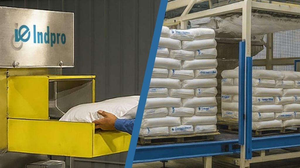
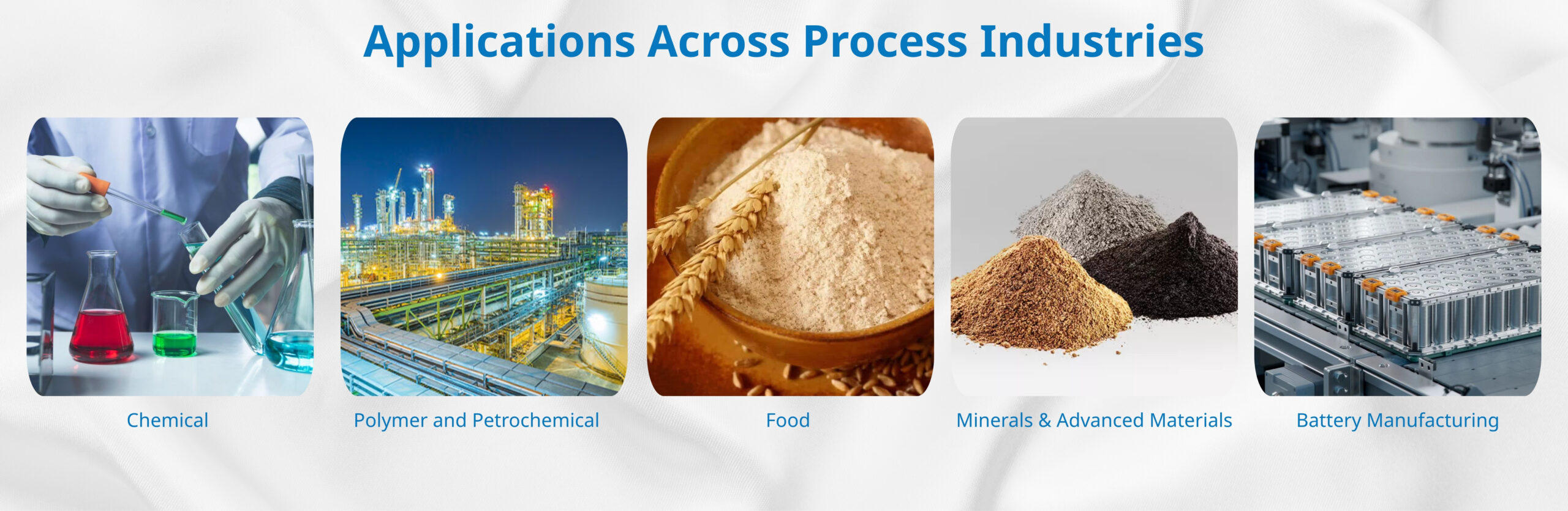
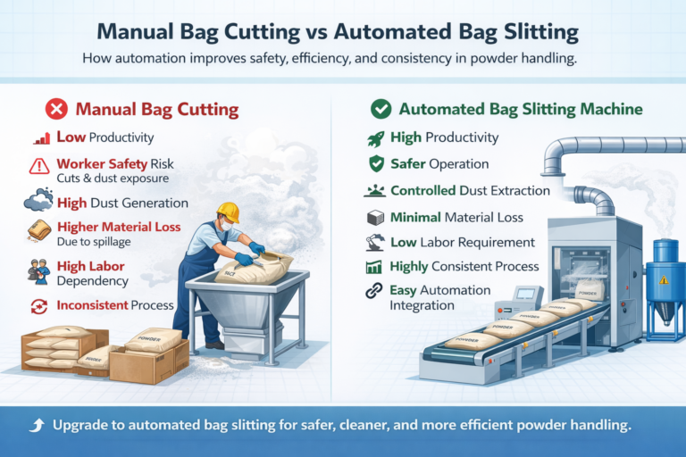
In modern bulk solids processing industries – such as polymers, chemicals, food ingredients, minerals, and petrochemicals – raw materials frequently arrive in bags ranging from 10 kg to 50 kg. While bagged material provides logistical flexibility, it introduces a major operational challenge inside the plant: safe, efficient, and contamination-free emptying of bags into the process stream.
Historically, this task relied heavily on manual bag opening, which introduced inefficiencies, safety risks, and product losses. As plants scale up production and prioritize automation, Automatic Bag Slitting Machines have become critical equipment in the bulk handling ecosystem.
However, designing a high-performance bag slitting machine is not merely about cutting bags. It requires a carefully engineered system that integrates mechanical design, process flow, safety engineering, and material behavior considerations.
This article explores the design engineering principles behind Automatic Bag Slitting Machines, providing insight into how modern machines achieve high efficiency, safety, and reliability.
The Role of Bag Slitting Machines in Industrial Processing
Bag slitting machines function as the entry point for bagged raw materials into automated production lines. Their primary function is to
• Open sealed bags automatically
• Separate packaging material from product
• Recover nearly all product inside the bag
• Discharge the material into the process stream
Typical downstream systems include:
• Pneumatic conveying systems
• Rotary airlock valves
• Vibro sifters
• Process mixers
• Storage silos
In high-capacity plants, bag slitting machines may process hundreds to thousands of bags per hour, making them a critical component for maintaining continuous production flow.
Fundamental Design Objectives
The engineering design of a bag slitting machine must achieve several objectives simultaneously.
• High Throughput: Industrial systems must handle large volumes of bagged materials without bottlenecks. Typical capacities range from: 300 to 1500 bags per hour depending on bag size and material characteristics.
• Maximum Product Recovery: Ideally, the machine should recover more than 99% of the material inside the bag, minimizing product losses.
• Reliable Bag Separation: Empty bags must be removed effectively without contaminating the product stream.
• Dust Containment: Powder materials can generate significant dust during bag opening, requiring engineered dust control systems.
• Operator Safety: The machine must eliminate risks associated with:
• Rotating blades
• Moving conveyors
• Falling bags
Meeting these objectives requires a multi-disciplinary engineering approach.
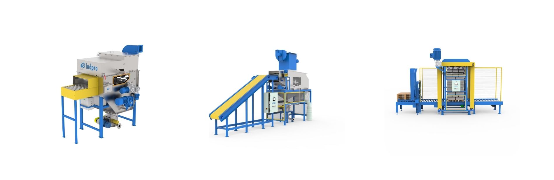
Key Modules in Automatic Bag Slitting Machine Design
A well-engineered bag slitting machine consists of several integrated modules working together as a cohesive system.
The major engineering modules include:
1. Bag feeding system
2. Slitting mechanism
3. Bag separation system
4. Product discharge hopper
5. Dust extraction system
6. Bag compaction or discharge unit
7. Automation and control system
Each module plays a crucial role in achieving reliable operation.
1. Bag Feeding System Design
The feeding system determines how bags enter the slitting chamber, directly influencing throughput and operational stability.
Feeding Methods
Common feeding arrangements include:
• Manual bag loading onto conveyors
• Roller conveyor feeding
• Belt conveyor feeding
• Automatic bag depalletizing systems
• Robotic bag handling systems
Engineering Considerations
Bag Orientation Control: Bags must be oriented correctly before entering the slitting zone to ensure consistent cutting.
Structural Strength: Industrial machines must support continuous loads of 25–50 kg bags, requiring reinforced conveyor structures.
Flow Synchronization: The feeding system must synchronize with the slitting mechanism and downstream material handling equipment.
Poor synchronization can lead to:
• Machine choking
• Bag accumulation
• Irregular throughput
Modern designs often incorporate variable speed drives (VFDs) to optimize feed rates.
2. Slitting Mechanism Engineering
The slitting mechanism is the core functional element of the machine.
It is responsible for accurately cutting open the bag without excessive shredding or product loss.
Blade Design Options: Various blade types are used depending on bag construction.
Common blade designs include:
• Rotary cutting blades
• Fixed knife blades
• Serrated blades
• Multi-blade cutting arrays
Each blade type is suitable for different bag materials.
Blade Positioning
The blade system must ensure:
• Full bag opening
• Controlled cutting depth
• No tearing off bag material
Precision blade positioning helps prevent:
• Partial cuts
• Bag wrapping around blades
• Product spillages
Modern machines allow adjustable blade configurations to accommodate different bag types.
3. Engineering the Bag Separation System
After the bag is slit open, the next challenge is to separate the empty bag from the discharged material.
This stage is critical to ensure that bag fragments do not contaminate the product stream.
Separation Technologies: Several separation technologies are used in bag slitting systems –
• Rotating Drum Screens: A rotating perforated drum allows product to pass through while retaining bag fragments.
• Vibratory Screens: Vibration assists in separating powder materials from bag pieces.
• Mechanical Rake Systems: These systems pull empty bags away from the material flow.
Design Challenges
Effective separation must address:
• Sticky or cohesive powders
• Large bag fragments
• High throughput rates
Advanced designs incorporate self-cleaning screen mechanisms to prevent clogging.
4. Material Discharge and Flow Engineering
Once the product is separated from the bag, it must flow smoothly into downstream equipment.
However, bulk solids rarely behave like liquids, and improper design can lead to severe flow problems.
Key Factors in Hopper Design
Engineers must consider:
• Angle of repose
• Bulk density
• Particle size distribution
• Moisture content
• Cohesiveness of the material
These factors influence hopper geometry.
Hopper Configurations
Typical hopper types include:
• Conical hoppers
• Pyramid hoppers
• Mass-flow hoppers
Correct hopper design prevents:
• Material bridging
• Rat-holing
• Inconsistent discharge
Reliable material flow ensures uninterrupted downstream processing.
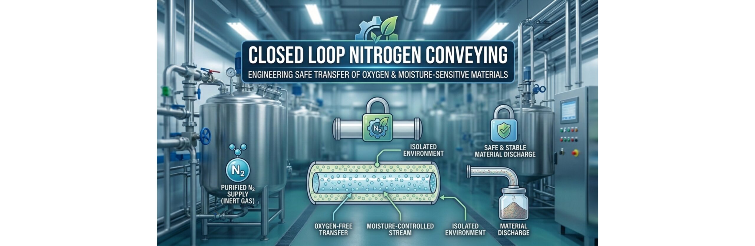
5. Dust Control Engineering
Dust generation is a major concern when handling powdered materials.
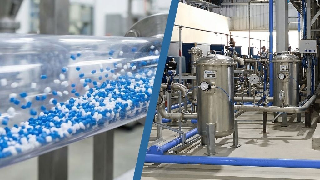
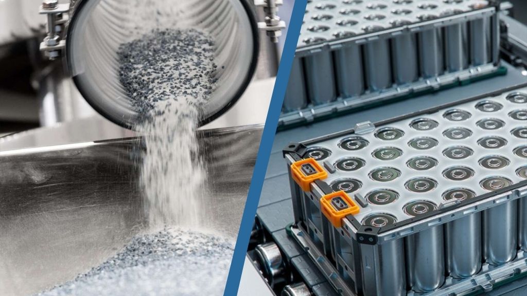
Materials such as:
• Polymers
• Pigments
• Silica
• Chemicals
• Flour and starch
can generate airborne dust during bag slitting operations.
Dust Control Strategies: Effective dust management systems include:
• Sealed Slitting Chambers: Enclosing the cutting area prevents dust escape.
• Negative Pressure Zones: Dust extraction systems maintain negative pressure inside the machine.
• Integrated Dust Extraction Ports: These ports connect to plant dust collectors.
Benefits of Dust Control
Proper dust management provides:
• Improved operator safety
• Reduced product losses
• Compliance with environmental regulations
In certain industries, dust control is also critical for explosion prevention.
6. Safety Engineering in Bag Slitting Machines
Safety is a fundamental requirement in industrial equipment design.
Bag slitting machines contain below parts which pose potential hazards:
• Rotating blades
• Moving conveyors
• Heavy bags
Modern machines incorporate-
• Interlocked Access Doors: The machine stops automatically if access doors are opened.
• Emergency Stop Systems: Strategically placed emergency stop buttons allow immediate shutdown.
• Blade Guards: Protect maintenance personnel during service operations.
• Jam Detection Sensors: Sensors detect abnormal loads and stop the machine to prevent damage.
Safety engineering must comply with international standards such as:
• ISO safety guidelines
• CE machinery directives
• OSHA safety regulations
7. Handling Diverse Bag Types
Industrial plants often receive materials in different bag formats.
Common bag constructions include:
• Multi-wall paper bags
• Woven polypropylene bags
• Polyethylene bags
• Laminated composite bags
• Raffia bags
Each bag type behaves differently when cut.
Engineering Adaptability
High-performance bag slitting machines offer:
• Adjustable blade configurations
• Flexible feeding mechanisms
• Modular separation systems
This flexibility allows the machine to handle multiple bag formats without extensive reconfiguration.
8. Automation and Control Systems
Automation significantly enhances the efficiency and reliability of bag slitting machines.
PLC-Based Control Systems
Modern machines use programmable logic controllers (PLCs) to manage:
• Bag feeding speed
• Blade operation
• Jam detection
• Emergency shutdown procedures
Advanced Monitoring Features
Smart systems may include:
• Bag counting systems
• Load monitoring sensors
• Real-time throughput tracking
• Predictive maintenance alerts
Integration with SCADA or plant-wide control systems allows centralized monitoring of operations.
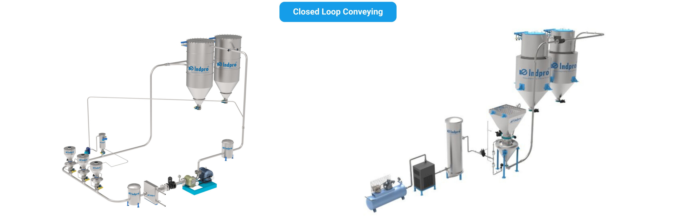
9. Integration with Downstream Process Equipment
A bag slitting machine rarely operates as a standalone unit.
Instead, it functions as part of a larger bulk solids handling system.
Typical integration includes:
• Pneumatic conveying systems
• Rotary airlock valves
• Vibro sifters
• Storage silos
• Process mixers
Proper engineering integration ensures:
• Smooth material transfer
• Minimal dust generation
• Balanced system throughput
Incorrect integration can create process bottlenecks and material flow disruptions.
Performance Metrics and Industrial Expectations
To evaluate system performance, several key metrics are used.
| Performance Parameter | Typical Industrial Value |
|---|---|
| Throughput | 300–1500 bags/hr |
| Bag Weight Range | 10–50 kg |
| Product Recovery | >99% |
| Bag Separation Efficiency | >98% |
| Dust Emission | Minimal with extraction |
High-performance systems maintain consistent performance even under continuous industrial duty cycles.
Emerging Innovations in Bag Slitting Technology
With the rise of Industry 4.0, bag slitting machines are evolving beyond purely mechanical equipment.
Future systems may incorporate:
• Robotic Bag Feeding: Automated robotic arms can depalletize bags and feed them directly into slitting machines.
• AI-Based Jam Detection: Machine learning algorithms can detect early signs of equipment malfunction.
• Automated Bag Compaction: Empty bags can be automatically compacted to reduce waste handling volume.
• Real-Time Production Monitoring: Operators can track system throughput and performance remotely.
These innovations are transforming bag slitting machines into smart nodes within digital manufacturing ecosystems.
Conclusion
Automatic Bag Slitting Machines are a vital link between bagged raw material logistics and automated industrial production.
Their design requires a deep understanding of:
• Mechanical engineering
• Bulk material flow science
• Safety engineering
• Dust management
• Automation technology
A well-designed system ensures:
• High throughput
• Minimal product losses
• Improved plant safety
• seamless integration with downstream processes
As industries move toward greater automation and digitalization, the design engineering of bag slitting machines will continue to evolve – playing a key role in the future of efficient bulk material handling.