Indpro Logo

Indpro
Typically replies within an hour

Indpro
"Hello!👋

How can I help you today with your bulk material handling needs?"
×
Chat with Us

What is Weighing & Batching Hopper?

What is Weighing & Batching Hopper?

The weighing & batching hopper stands as a cornerstone of precision in industrial processes where accuracy and efficiency are paramount. It is an integral part of many manufacturing processes, contributing to the consistency and reliability of the measurement and dispensing of materials. In this blog, we explore weighing & batching hoppers, product dosing methods, and the components of weighing & batching systems to explore what weighing & batching is all about.

Understanding weighing & batching:

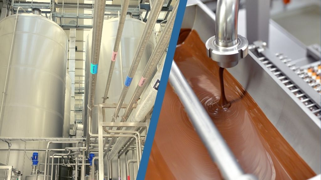
Weighing & batching is a method of dispensing materials in predetermined quantities by weight. This precise approach is crucial in industries where the composition and consistency of products are paramount, such as pharmaceuticals, food processingchemicals, and more. Weighing & batching ensures that the correct proportions of raw materials are used in each batch, leading to consistent product quality.

What is a Weighing & batching Hopper?

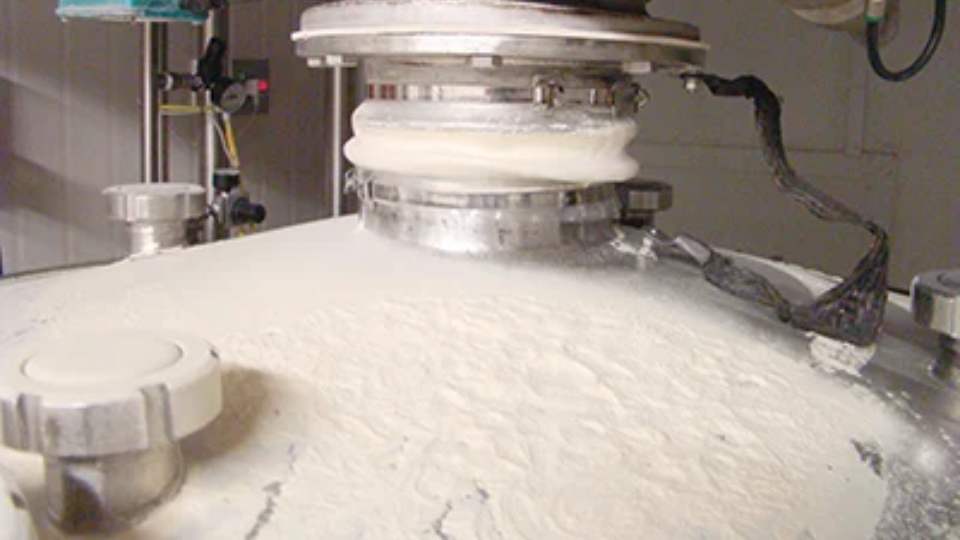
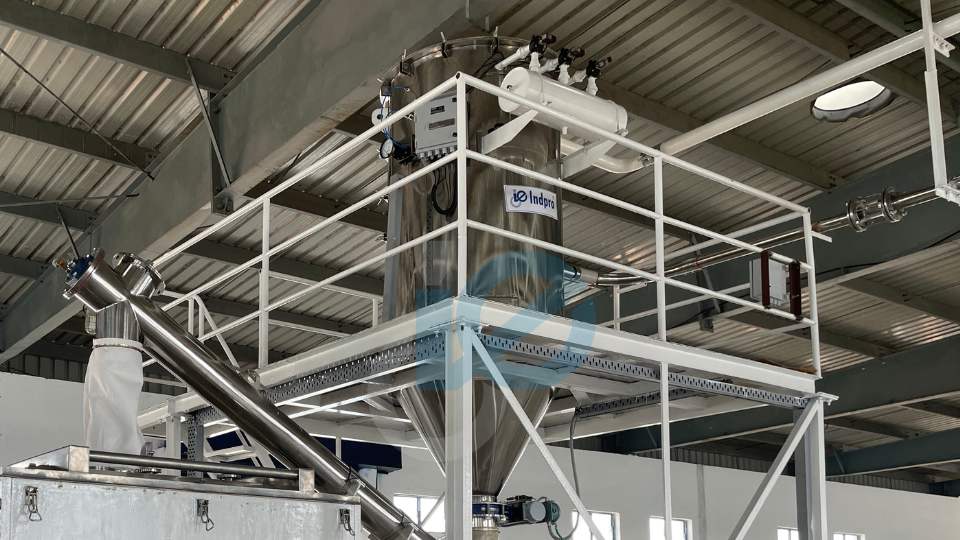
A weighing & batching hopper is at the heart of a weighing & batching system. Based on the weight of the material, this vessel is designed to hold and measure the desired quantity of material. This material can be accurately dosed using the hopper’s load cells or weight measurement devices, which provide real-time feedback to the control system.

Product Dosing Methods

In weighing & batching hoppers, materials are dispensed accurately using various dosing methods. In choosing a dosing method, factors such as material nature, accuracy requirements, and overall manufacturing process need to be considered. Common dosing methods include:

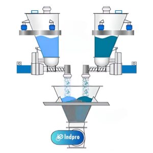
Gain-in-Weight Dosing:

In this method involves filling the weighing & batching hopper with the material gradually until the target weight is reached. Throughout the feeding process, the system monitors the weight gain and adjusts the feeding rate accordingly.

gain in weight feeder -indpro

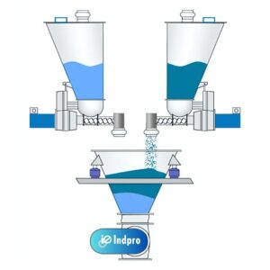
Loss-in-Weight Dosing:

The loss-in-weight method begins with a full hopper, and material is gradually removed until the desired weight is reached. The system monitors the weight loss and adjusts the feed rate accordingly.
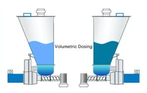
loss in weight feeder - indpro

Volumetric Dosing:

Volumetric dosing relies on measuring the volume of material rather than its weight. It is simpler than weight-based dosing, but less accurate than that, and often used in non-critical situations.

Volumetric-Dosing system - indpro

Components of a weighing & batching System:

Weighing & batching Hopper:

The central component, the weighing & batching hopper, is designed to securely hold and measure the materials based on weight.
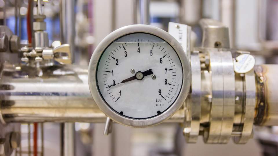
Load Cells:

Load cells are sensors integrated into the weighing & batching hopper, providing real-time weight measurements. These measurements are crucial for accurate dosing.
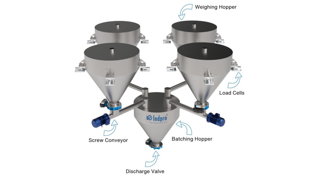
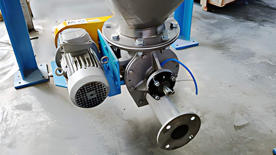
weighing & batching components - indpro

Feeding Mechanism:

The feeding mechanism, such as a conveyor belt or screw feeder, is responsible for transporting materials into the weighing & batching hopper at the desired rate.

Control System:

The control system oversees the entire weighing & batching process. The microcontroller interprets data from load cells, adjusts the feed rate as required in coarse feed & fine feed, and ensures that the correct quantity of material is dispensed.

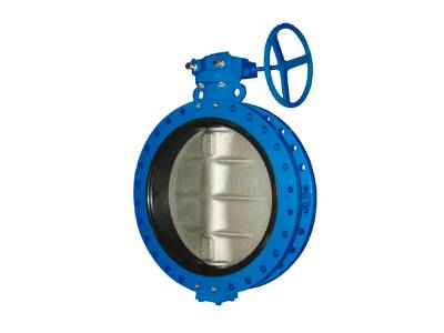
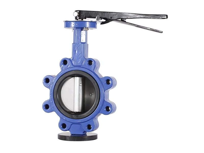
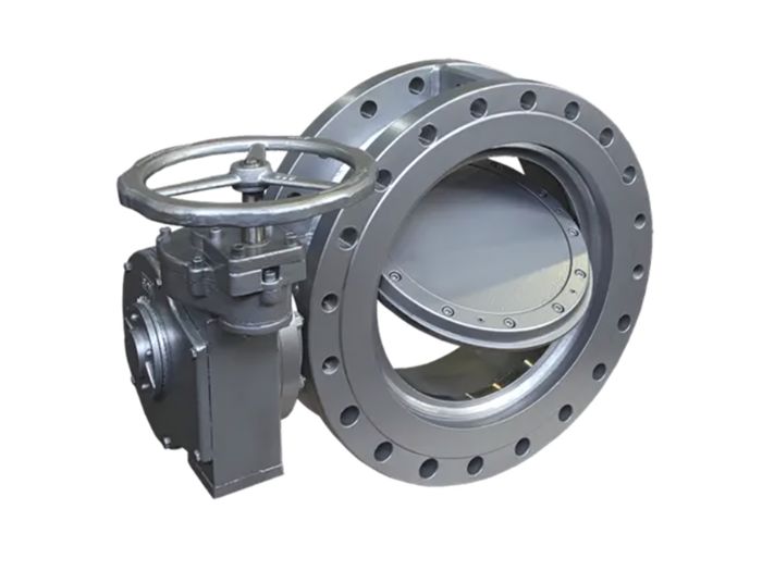
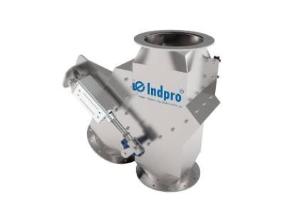
Discharge Mechanism:

Once the correct weight is achieved, the discharge mechanism, often a gate or valve, releases the materials from the weighing & batching hopper into the downstream process.

Calibration of Weighing & Batching Hopper

Weigh hopper calibration can be performed using different methods, and two common approaches are static test weigh calibration and material tests. Each method has its advantages and may be chosen based on factors such as the application, the type of material being handled, and the precision required. Here’s an overview of both methods:

1. Static Test Weigh Calibration:

Procedure:​

Advantages:

Considerations:

This method assumes that the weighing system behaves consistently under static conditions, and the material properties do not significantly affect the calibration.

2. Material Tests:​

Procedure:​​

Advantages:

Considerations:

  • Material tests may be more time-consuming and may require careful control of the material flow to ensure accurate results.
  • The material used for testing should be representative of the materials the system will handle in normal operations.

Advantages of Weighing & batching:

In the symphony of industrial processes, the weighing & batching hopper plays a virtuoso role, ensuring harmony and precision. From pharmaceutical formulations to food recipes, the reliability and accuracy of weighing & batching systems are indispensable. As industries continue to prioritize consistency and efficiency, the weighing & batching hopper stands as a testament to the art and science of precision manufacturing, shaping the landscape of diverse industrial sectors.

Increasing the Lifespan of Bulk Material Handling System

Increasing the Lifespan of
Bulk Material Handling System

In industrial operations, where efficiency and longevity are paramount, the lifespan of bulk material handling systems plays an important role in determining overall productivity. From conveyors to storage silos, these systems form the backbone of material transport in various industries. The focus of this blog is to understand how to increase the lifespan of bulk material handling systems, ensuring sustained performance, and minimizing downtime.

The Crucial Role of Maintenance:

The key to a reliable and efficient bulk material handling system is a well-executed maintenance strategy. Regular maintenance prevents unexpected breakdowns and costly downtime, as well as extending the lifetime of critical components. Here are some key aspects of an effective maintenance strategy.​

Regular Inspections:

Ensure that all pneumatic conveying components, such as pipe connections, valves, filters, and rotary airlock valves, are routinely inspected visually. Inspect your system for signs of wear, leaks, obstructions, or abnormalities.

Filter Inspection and Cleaning:

Keep filters clean and inspect them regularly to prevent dust buildup and maintain proper airflow. Clogged filters can lead to reduced system efficiency and increased pressure drop. Although most filters nowadays come with pulse jet cleaning technology, some process changes can lead to clogging of filters.

Check Seals and Gaskets:

Periodically inspect the seals and gaskets in rotary airlock valves, diverter valves, and other components. Any worn or damaged seals should be replaced to prevent air leaks and maintain the system’s performance.

Rotary Valve Maintenance:

When your system includes rotary airlock valves, conduct regular maintenance. Clean and inspect the valves, replacing any parts, such as rotor blades and seals, that show wear or damage.

Rotary Valve Maintenance

Inspect Pneumatic Conveying Pipes:

Inspect pneumatic conveying pipes for signs of wear, corrosion, or damage. Promptly address any issues to prevent leaks and maintain the system’s integrity.

Lubrication:

Lubricate moving parts, including bearings, chains, and pneumatic actuators, as per the manufacturer’s guidelines. Proper lubrication ensures smooth operation and minimizes wear.

Air Compressor and Blower Maintenance:

Perform regular maintenance on the air compressor and blower. This includes changing filters, checking oil levels, and inspecting for signs of wear or malfunction. This is the most essential device that is responsible for running the system.

Check Pressure Relief Devices:

Ensure that pressure relief devices, such as safety valves, are functioning correctly. These devices are crucial for preventing over pressurization in the system.

Material Leakage Prevention:

Address any material leakage issues promptly. Material leaks can lead to product loss, contamination, and safety hazards.

powder Leakage Prevention solution

Inspect Instrumentation and Controls:

Regularly inspect and test instrumentation, sensors, and control systems to ensure they are accurate and functioning correctly. Calibrate instruments as needed.

Inspect Pneumatic Conveying Fans:

If the system includes fans or blowers, inspect and maintain these components regularly. Check for proper alignment, clean fan blades, and ensure the motor is functioning as intended.

Vibration Analysis:

Perform vibration analysis on rotating equipment, such as fans and blowers, to detect imbalances or misalignments that could lead to equipment failure.

Training and Documentation:

Provide training to operators and maintenance personnel on the proper operation and maintenance of the pneumatic conveying system. Maintain comprehensive documentation, including manuals, maintenance schedules, and records of repairs.

Emergency Preparedness:

Establish and communicate emergency procedures, including shutdown protocols and response plans. Make sure that personnel are trained on emergency response.

System Optimization:

Periodically review and optimize the pneumatic conveying system to improve efficiency. Consider adjustments to air velocities, conveying parameters, and system configurations based on changing requirements.

Importance of Maintenance:

Maintenance is critically important for bulk material handling systems for several reasons, and its significance can be summarized as follows:

1. System Reliability:

Regular maintenance is essential for ensuring the reliability of bulk material handling systems. By addressing potential issues before they lead to breakdowns, the system can operate consistently and meet production demands.

2. Prevention of Downtime:

Downtime in a bulk material handling system can be costly in terms of lost production and revenue. Proper maintenance helps prevent unscheduled downtime by identifying and addressing issues proactively.

3. Equipment Longevity:

Well-maintained equipment tends to have a longer lifespan. Regular inspections, lubrication, and part replacements contribute to the longevity of components, reducing the need for frequent replacements.

4. Operational Efficiency:

Maintenance makes sure that the system operates at optimal efficiency. This includes addressing issues such as misalignments, wear and tear, and material buildup, which can otherwise lead to reduced throughput and increased energy consumption.

5. Safety Compliance:

Maintenance is essential for ensuring that the bulk material handling system complies with safety standards and regulations. Regular inspections and repairs contribute to a safe working environment for personnel.

6. Cost Savings:

Investing in preventive maintenance is more cost-effective than handling emergency repairs and replacements. Regular maintenance tasks are usually cheaper and can help avoid expensive major failures.

7. Product Quality:

Maintenance is essential for ensuring that the bulk material handling system complies with safety standards and regulations. Regular inspections and repairs contribute to a safe working environment for personnel.

8. Energy Efficiency:

Properly maintained systems tend to operate more efficiently, leading to energy savings. Addressing issues such as misalignments and friction can reduce energy consumption and contribute to overall sustainability efforts.

9. Minimization of Unscheduled Repairs:

Unscheduled repairs can be disruptive and expensive. Maintenance activities help minimize the occurrence of unexpected breakdowns, allowing for planned repairs and replacements during scheduled downtimes.

In the dynamic sector of bulk material handling, where efficiency and reliability are crucial, a solid maintenance strategy is essential for success. Prioritizing routine inspections, effective lubrication, thorough cleaning, and predictive maintenance technologies ensures the efficiency and longevity of material handling systems. Maintenance is not just a reactive measure but a proactive investment in operational resilience and industrial success. As industries progress, a well-maintained material handling system is key to smooth and efficient material transport.

Types of valves used in pneumatic conveying systems

Types of valves used in
pneumatic conveying systems

Valves play a crucial role across various industries, serving to control the flow of gas and fluid through specific connection lines. With diverse types and functions, valves aid in redirecting or restricting the flow of substances within a system.

Industrial valves are designed to regulate, start, change, separate, or stop the flow of fluid or gas in a set direction. Besides that, they can also help ease excessive pressure from different vessels or systems.

There’s a whole variety of valve types for all wide range of applications. If you’re dealing with industrial setups that use valves for different reasons, understanding the various types is key. Let’s check out the different kinds of industrial valves!

Type of valves used in Pneumatic Conveying System


1. Butterfly Valve: ​ ​​

A butterfly valve is a quarter-turn valve used to control fluid flow in a pipeline. It’s called “butterfly” because the disc inside looks like a butterfly’s wings when it rotates. This disc sits in the middle of the pipe and when turned 90 degrees, it either allows or blocks the fluid flow. These valves are great for isolating vessels or in pneumatic conveying pipelines for handling bulk solids.

Butterfly valves are differentiated in terms of type of construction in the following ways:

Concentric Butterfly Valve

It is the most common type of butterfly valve the where, the shaft which connects the actuator to the disc of butterfly valve known as ‘stem’ is positioned at the center of the disc.

Lug-style Butterfly Valve

This valve has threaded inserts at both sides of the valve body. The valve is mounted between two flanges.

Eccentric Butterfly Valve

The stem of this valve is located off-center, which allows for a more resilient seating arrangement. There are two types: high-performance valves and triple offset valves. High-performance eccentric valves have a slightly offset stem, while triple offset valves have a more pronounced offset.

Wafer-style Butterfly Valve

This valve is designed to fit between two flanges without the need for bolts and nuts through the flange holes, typically 4 in number. It is held in place by the flanges.

Flanged Butterfly Valve

This valve is installed between two flanges using bolts and nuts to secure it in place. It is suitable for applications where the pipeline has flanges at both ends.

Butterfly valves are widely used in various industries due to their simplicity, lightweight design, and relatively low cost. They are suitable for applications where tight shut-off is not critical, and a quick quarter-turn operation is desirable.


2. Knife Gate Valve: ​​

A knife gate valve is a special type designed to cut through thick fluids using an edge blade. These valves are commonly used when you need straight-line fluid flow with minimal restrictions. They’re also used for isolating vessels or feeders handling bulk solids. They are typically designed for heavy loads.

The main types of knife gate valves used are:

Slurry Knife Gate Valve

Specifically designed to handle abrasive and viscous slurry fluids. The gate is designed to cut through the slurry without causing excessive wear.

Uni-Directional Knife Gate Valve

Flow is restricted in one direction only. This type is suitable for applications where a one-way flow is desired.

Bi-Directional Knife Gate Valve

Flow can occur in both directions. It provides versatility in applications where fluid flow may need to change directions.

Lug-Style Knife Gate Valve:

Like lug-style butterfly valves, these valves have threaded inserts at both sides of the valve body. Typically used in applications where the valve is positioned between two flanges.

Wafer-Style Knife Gate Valve

This valve is designed to fit between two flanges without the need for bolts and nuts through the flange holes, typically 4 in number.


3. Ball Valve: ​​​​ ​

Ball valves have a design with a big sphere and central hole for smooth fluid flow. They’re great at controlling high-pressure liquids and gases while reducing pressure drop. Their quick response time makes them efficient for fast opening and closing actions. Ball valves are versatile and perfect for different pneumatic conveying system applications. Here are some common types of ball valves used in pneumatic conveying:

The main types of ball valves used are:

Two-way (shut-off) ball valve

controls the flow of air or gas in a straight-through path. It allows the system to start and stop as needed.

Three-Way (Diverter) Ball Valve

These valves have three ports and can redirect the flow of air or material between two different paths. Used for diverting air flow to different destinations within the pneumatic conveying system.

V-Port Ball Valve

These valves have a V-shaped port in the ball, allowing for more precise control of flow by partially opening or closing the valve. Used in applications where throttling or modulating the flow is required.

Full-Port Ball Valve

These valves have a larger port size, providing minimal restriction to flow and reducing pressure drop. Suitable for applications where maximizing flow capacity is important.

Trunnion-Mounted Ball Valve

provides additional support for the ball , ensuring stability and reducing pressure on it . Used in high-pressure pneumatic conveying systems.

Metal-Seated Ball Valve

These valves have metal seats, providing better wear resistance and durability, especially in applications with abrasive materials. Suitable for handling abrasive materials in pneumatic conveying systems.

Floating Ball Valve

The ball in these valves is not fixed and can move slightly to ensure a tight seal against the seats. Used in applications where a tight seal is crucial to prevent leakage.

Cavity Filled Ball Valve

These valves have a cavity filled with a sealing material to enhance sealing performance. Suitable for applications requiring enhanced sealing in pneumatic conveying.

Butterfly, ball and knife gate valves can be operated using various methods, including manually, electrically, pneumatically, or hydraulically. The choice of actuation method depends on the specific application requirements and the preferences of the system designer. These valves are commonly actuated by the following methods:

1. Manual Operation:

Handwheels or levers are used to manually turn the stem and control the position of the disc or gate.

2. Pneumatic Operation:

Compressed air is used to actuate the valve. Pneumatic actuators are common for these valves, especially in applications where quick and efficient operation is needed.

3. Hydraulic Operation:

Hydraulic systems use fluid pressure to actuate the valve. Hydraulic actuators provide more force and are suitable for larger valves or applications with higher operating pressures.

4. Electric Operation:

Electric motors drive the valve’s actuator. Electrically operated valves are suitable for applications where continuous modulation of the valve position is required.

The choice between hydraulic, pneumatic, or electric actuation depends on factors such as the size of the valve, the required operating pressure, the speed of operation, and the automation level desired for the system. In many cases, pneumatic actuation is a popular choice for these valves due to its simplicity, cost-effectiveness, and the ability to provide rapid on/off control.


4. Diverter Valve: ​​ ​

Diverter valves are classified based on their diverter mechanism and application. Three common types of diverter valves are:

This type finds its application for flow of bulk solids due to gravity, facilitating diversion to multiple destinations, in a vertical format. It is ideal for scenarios where the movement of bulk solids needs to be directed to various receiving points. These are typically operated using a pneumatic actuator.

Primarily used in pneumatic conveying systems and bulk solids handling applications of powder or granular material to redirect the flow from a single inlet to two separate outlets or vice versa. The versatility allows this unit to be mounted in any direction, depending on the configuration of the pipeline. It diverts dense or lean phase solids conveying to various destinations without disrupting the gas flow. These can be used up to a pressure of 6 bar(g) in usual applications. These are typically operated using a pneumatic actuator.

Single Tunnel Diverter Valves​

Similar in application to a dual tunnel diverter valve, however instead of having 2 tunnels on the inside, this unit consists of just 1 tunnel. For larger sizes, this design is better suited since it is more compact and easier to maintain.


5. Non-Return Valve:

Non-return valves, also known as check valves, are essential in pneumatic conveying systems to allow one-way flow of air while preventing backflow of either air or material. Common types include swing check valves, lift check valves, spring-loaded check valves, in-line check valves, diaphragm check valves, disc check valves, wafer check valves, and dual-plate check valves. Their selection depends on factors like material type, system pressure, and application orientation. These valves play a crucial role in maintaining system efficiency and preventing issues such as material contamination and equipment damage.


6. Pressure Regulating Valve: ​

In pressure regulating valves, high-pressure fluid or gas initiates the process. A spring within the valve exerts a consistent force to slightly open it. This allows the fluid or gas to flow through, filling the outlet end. As the outlet pressure builds, it pushes the valve upward, closing it. Essential in industrial processing, water distribution, and steam systems dealing with high pressure.

Pressure regulating valves in pneumatic conveying systems control and maintain a consistent pressure of conveying air or gas. They come in direct-acting and pilot-operated types, with an adjustment mechanism for setting desired pressure levels. These valves prevent over pressurization, contribute to system efficiency, and can be integrated into control systems for automated adjustments. Proper selection, installation, and maintenance is crucial for reliable pneumatic conveying performance.


7. Pressure Relief Valve: ​

Pressure relief valves in pneumatic conveying systems automatically release excess pressure to prevent over pressurization, safeguarding equipment from damage. They come in direct-acting and pilot-operated types, with a set pressure point for activation. These valves serve as safety features, protecting pipelines and components. Some models reset automatically, while others may require manual intervention. Compliance with safety standards and regular maintenance is crucial for their effective operation in pneumatic conveying applications.


8. Solenoid Valve

Solenoid valves are essential in pneumatic conveying systems for controlling the flow of air or gas. They operate electromechanically, responding to electrical signals to open or close. Types include Normally Closed (NC), Normally Open (NO), Three-Way, and Four-Way valves. They play roles in diverting airflow and integrating with control systems. Solenoid valves are chosen based on pressure ratings, material compatibility, voltage requirements, and response times, contributing to the efficiency and automation of pneumatic conveying systems. Regular maintenance is crucial for their reliable operation.

Dedusting System for Plastic Pellets

Dedusting System for Plastic Pellets

In the plastic manufacturing industry, maintaining product quality and manufacturing efficiency is paramount. One critical aspect of this is the management of dust and streamers, which are commonly generated during the pneumatic conveying process or during mixing and blending operations. To address this, an effective plastic pellet dedusting system is essential.


Sources of Dust and Streamers

Dust and streamers in the plastic industry primarily arise from two types of pneumatic conveying processes:

This method involves material transfer at high speeds, resulting in increased dust and streamer production. The swift motion induces abrasion and friction, degrading pellets into fine particles and streamers.

Although generating less dust and streamers due to lower velocities, this method still produces fine particles that require removal to ensure high product quality.

During the mixing and blending of plastic pellets, mechanical agitation can cause friction and impact, resulting in the generation of dust and streamers. The interaction of materials in these processes often breaks down the pellets, contributing to dust formation.


Impact of Dust and Streamers

The presence of dust and streamers can trigger various adverse effects in the plastic manufacturing process:

Surface Blurring

Vaporized dust particles can blur the surface of final plastic products, impacting their appearance and aesthetic appeal.

Increased Scrap Rates

Fine particles may burn within molds, leading to heightened scrap rates and reduced manufacturing efficiency.

Wire Insulation Defects

Dust can provoke defects in wire insulation, jeopardizing the safety and functionality of electrical components.

Gel Formation in Films

Dust presence may instigate gel formation within plastic films, influencing clarity and uniformity.

Sink Marks on Parts

Dust accumulation in molds can result in unsightly sink marks on plastic parts, affecting their structural integrity and visual appeal.


How Dedusting system for plastic industry works:

The New Patented technology of Plastic Pellet Dedusting system PelletPurge® is specially designed to clean plastic pellets by removing dust and streamers, setting a new benchmark in plastic pellet manufacturing. Positioned strategically beneath storage silos before plastic processing or packing, it effectively eliminates impurities, enhancing the overall product quality. Embrace this cutting-edge solution with us and take your manufacturing processes to new levels with PelletPurge®! 


Applications for the Plastics Processing Industry​

  • Cleaning plastic pellets at the machine feed throat before Injection molding or extruder to ensure optimal optical clarity.
  • It can also clean pellets as they are fed into central surge bins or day bins, feeding multiple machines or dryers.
  • Whether at a cleaning station in a Railcar or truck unload system, drying process, regrinds operation, packaging area.
  • Even recycling plants, this system eliminates dust before loading into storage silos or processing equipment.
  • You can install PelletPurge® system under silos, loading hoppers of packing machines, extruder feed hoppers, or even on injection molding machines. Experience the efficiency and quality improvements that this system brings to the plastic industry!

High-Quality Fabrication – Key for the success of Pneumatic Conveying Systems

High-Quality Fabrication - Key for the success of
Pneumatic Conveying Systems

Fabrication manufacturing is an essential part of creating components crucial to the operation of pneumatic conveying systems (PCS). From Silo, hoppers to ductwork, these fabricated components are vital for the efficient transport of bulk materials across industries. Let’s explore the fabrication process and its significance in the world of PCS.


1. What is Fabrication? And Why is Fabrication Quality Important in Pneumatic Conveying Systems?

Fabrication involves the assembly of sheet metal parts to create products, structures, or components that meet specific design criteria. Key steps in the fabrication process include cutting, shaping, joining, and assembling sheet metals to achieve the desired form and function of the final product.

Pneumatic conveying systems are complex and require precise engineering and fabrication to function properly. Any flaws or imperfections in the fabrication process can lead to issues such as material buildup, blockages, and leaks, which can result in costly downtime and maintenance.


High-quality fabrication is essential for the success of conveying systems for the following reasons:

Efficient Material Flow:

The primary purpose of a pneumatic conveying system is to transport materials from one location to another. Any obstructions or irregularities in the hoppers and other storage devices can disrupt the flow of materials, leading to inefficiencies and potential system failures.

Proper fabrication techniques ensure that the surfaces in powder contact are smooth and free of any obstructions, allowing for efficient material flow and preventing costly downtime.

Durability and Longevity:

Pneumatic conveying systems are often used in industrial settings where they are subjected to harsh conditions and heavy use. This makes durability and longevity crucial factors in the success of these systems.

High-quality fabrication techniques, such as using corrosion-resistant materials and proper welding methods, can ensure that the system can withstand the demands of its environment and have a longer lifespan.

Safety:

Safety is a top priority in any industrial setting, and pneumatic conveying systems are no exception. Poor fabrication can lead to leaks, blockages, and other issues that can compromise the safety of workers and the surrounding environment, especially when handling hazardous powders.

By using high-quality fabrication techniques, the risk of accidents and injuries can be greatly reduced, making the workplace safer for everyone. Following the correct design and manufacturing practices for explosion protection is of paramount importance.


Key Fabrication Techniques for Pneumatic Conveying System Components

Achieving high-quality fabrication in pneumatic conveying requires a combination of advanced techniques and skilled craftsmanship. Here are some of the key techniques used in the fabrication of these systems:

Metal Shaping:

Metal shaping is a crucial step in the fabrication process of pneumatic conveying system components. It involves using various tools and techniques to bend, cut, and shape metal sheets into the desired form.

The most common metal shaping techniques include:

Rolling

This technique involves passing a metal sheet through a set of rollers to bend it into a cylindrical shape, which is commonly used for the fabrication of pipelines.

Bending

Bending is the process of using a press brake or other tools to create bends and angles in metal sheets.

Cutting

Cutting is used to trim metal sheets to the desired size and shape using tools such as shears, plasma cutters, or laser cutters.

Proper metal shaping is essential for creating a smooth and seamless component, which is crucial for efficient material flow in pneumatic conveying systems.

Welding:

Welding joins individual metal components together to form the final structure. It is a critical step in the fabrication of pneumatic conveying systems, as it is used to create airtight seals and ensure the structural integrity of the system. 

There are several welding techniques used in the fabrication including:

MIG Welding

MIG (Metal Inert Gas) welding is a popular technique that uses a wire electrode to create a strong and durable bond between metal pieces.

TIG Welding

TIG (Tungsten Inert Gas) welding is a more precise technique that uses a tungsten electrode to create a high-quality weld.

Resistance Welding

Resistance welding uses electrical resistance to join metal pieces together, making it a fast and efficient method for high-volume production.

Proper welding techniques are crucial for creating airtight seals and ensuring the structural integrity of the system, which is essential for the safe and efficient operation of conveying systems.

Finishing:

Finishing is the final step in the fabrication process of pneumatic conveying systems. It involves applying a protective coating or finish to the metal surfaces to improve their durability and resistance to corrosion.

Some of the most common finishing techniques used in the fabrication include:

Powder Coating

Powder coating involves applying a dry powder to the metal surface and then curing it with heat to create a durable and attractive finish.

Galvanizing

Galvanizing is the process of coating metal surfaces with a layer of zinc to protect them from corrosion.

Painting

Painting is a cost-effective finishing technique that involves applying a layer of paint to the metal surface to improve its appearance and protect it from corrosion.

Polishing

The surface is grinded to reduce the roughness of the surface, hence improving the look, finish, and smoothness.

Proper finishing techniques are crucial for ensuring the longevity and durability of pneumatic conveying systems, especially in harsh industrial environments.


Real-World Examples of High-Quality Fabrication in Pneumatic Conveying Systems

One example of high-quality fabrication in pneumatic conveying systems is the use of stainless steel for the construction of components. Stainless steel is a durable and corrosion-resistant material that is commonly used in the fabrication for the food, chemical and pharmaceutical industries.

Another example is the use of advanced welding techniques, such as TIG welding, to create airtight seals in the components of conveying systems. This ensures that there are no leaks or blockages that can disrupt the flow of materials and compromise the safety of the system.


Who is Responsible for Fabrication?

The responsibility for fabrication falls on a team of skilled professionals, including engineers, fabricators, and welders. These individuals work together to design, engineer, and fabricate the system to meet the specific needs of the client.


Which components of Pneumatic conveying system are fabricated?

In a pneumatic conveying system, various components are fabricated to ensure efficient operation. Some of the key components that are typically fabricated include:

1. Pipelines​:

The pipelines play a crucial role in transporting materials from one point to another in the system. Proper fabrication techniques are essential to create smooth and seamless pipelines to prevent material buildup and ensure efficient material flow.

2. Ductwork:​

Ductwork is used to direct the airflow and materials within the system. Fabrication of ductwork involves shaping and welding to create the necessary pathways for material or dust transportation.

3. Cyclones and Filters: ​

These components are essential for separating materials from the air stream. Fabrication techniques are used to create durable and efficient cyclones and filters to ensure proper separation and filtration.

4. Valves and Dampers: ​

Valves and dampers control the flow of materials within the system. Fabrication of these components involves precision machining and welding to ensure proper functioning and minimal air leakage.

5. Centrifugal Blowers:

These are crucial for generating the air flow and pressure needed to transport materials. Fabrication techniques are used to assemble and integrate these components into the system effectively.

6. Silo and Hoppers:

Fabrication of silos involves structural integrity considerations to withstand the weight of stored materials and environmental factors. Hoppers hold the materials before they are conveyed, while feeders regulate the material flow into the system. Fabrication of hoppers and feeders involves structural integrity and durability considerations.

7. Support Structures: ​

Support structures hold the components of the system in place. Fabrication techniques are used to ensure that these structures are stable and able to withstand the operational stresses of the system.

8. Screw feeders: ​

These are mainly used in the system for transportation of powders mechanically or as a feeder in the conveying line. Fabrication quality is essential in maintaining the clearance and effectiveness of the unit.

9. Material receipt components: ​​

Units such as bag dump stations, jumbo bag unloading systems and drum tilting stations, are used in conjunction with pneumatic conveying systems for powder unloading & transfer. The complex design and assembly of these units require good fabrication techniques.

10. Special devices: ​

There are many other components used as a part of the system, such as lump breaker, powder bridge breaker, bin activator, mixers, and many other. Fabrication techniques play a bigger role in ensuring quality of these products for use in the system.

High-quality fabrication is crucial for the success of pneumatic conveying systems. It ensures efficient material flow, durability and longevity, and the safety of workers and the surrounding environment. By using advanced techniques such as metal shaping, welding, and finishing, and working with a skilled fabrication team, you can ensure that your pneumatic conveying system is built to the highest standards and will provide reliable and efficient performance for years to come.