Indpro Logo

Indpro
Typically replies within an hour

Indpro
"Hello!👋

How can I help you today with your bulk material handling needs?"
×
Chat with Us

How to Design a Rotary Airlock Valve: Key Considerations for Bulk Material Handling

How to Design a Rotary Airlock Valve:
Key Considerations for Bulk Material Handling

Why Rotary Airlock Valves Matter

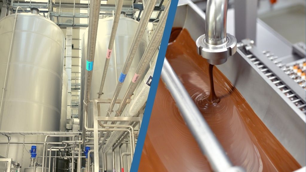
If you’ve worked in bulk material handling, you’ve surely come across the Rotary Airlock Valve (RAV). Think of it as the unsung hero of your system it regulates the flow of powders, granules, or pellets between two different pressure zones while minimizing air leakage. Whether in a pneumatic conveying line, dust collection system, or feeding process, the rotary valve ensures smooth, controlled material discharge.

But here’s the catch a poorly designed rotary valve can become a bottleneck. From excessive wear and tear to product leakage, the wrong design choice can cost you in downtime, maintenance, and money.

That’s why getting the design right matters. Before we dive into the key factors, let’s take a quick look at the types of rotary valves out there.


What is a Rotary Valve & What's in the RAV Family?

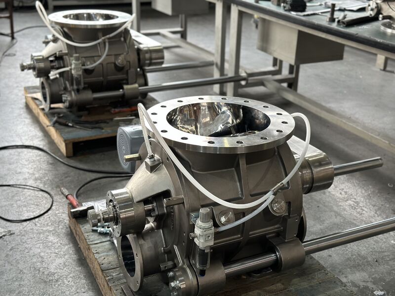
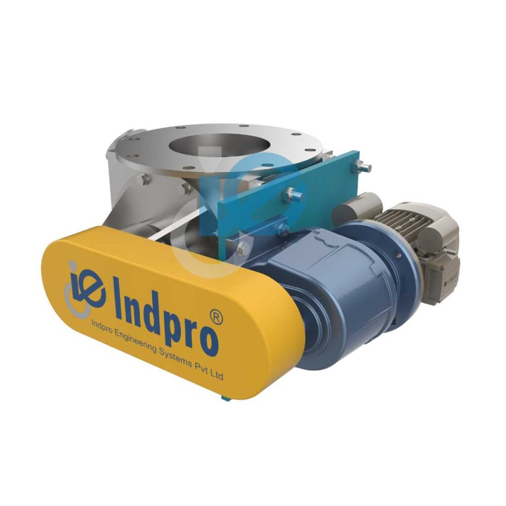
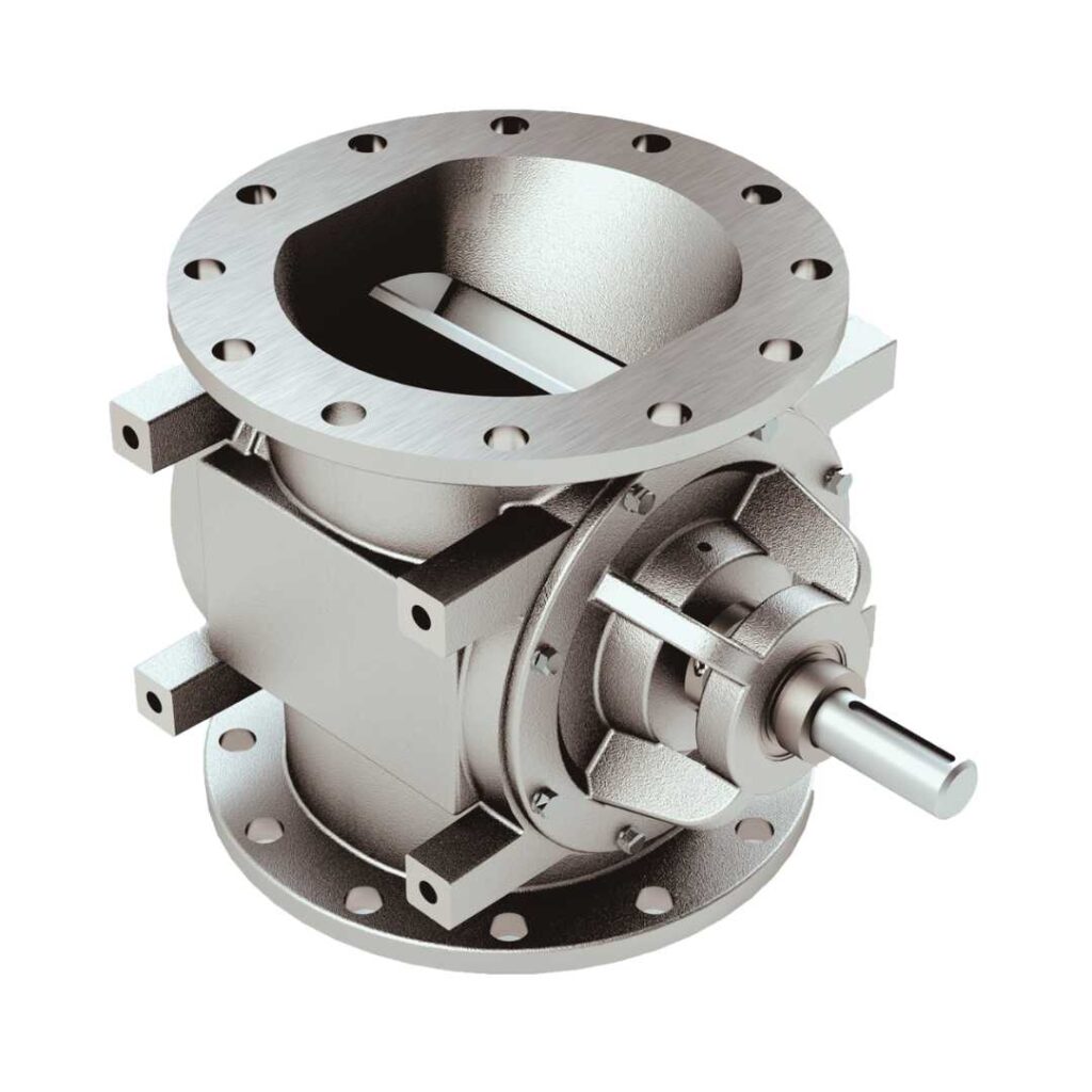
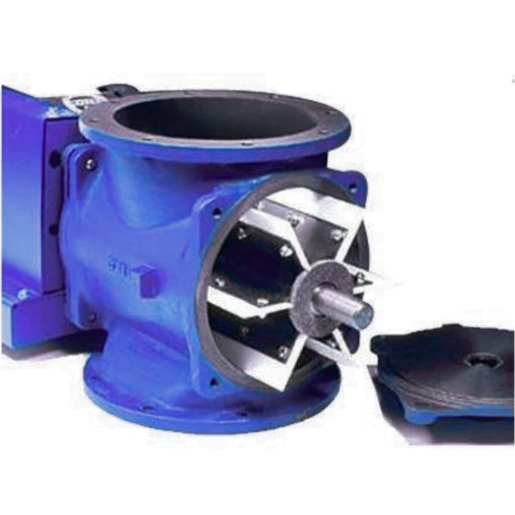
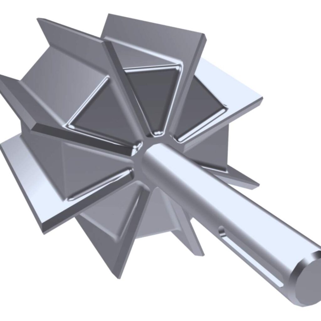
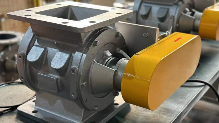
At its core, a rotary airlock valve (or RAV) is a simple machine. It consists of a vaned rotor that spins inside a cylindrical housing. As the rotor turns, the pockets between the vanes pick up material from the inlet above and drop it out of the outlet below, all while maintaining a pressure seal (the “airlock”).

Rotary valves aren’t one-size-fits-all. Depending on your process, material properties, and application, you’ll find different designs:

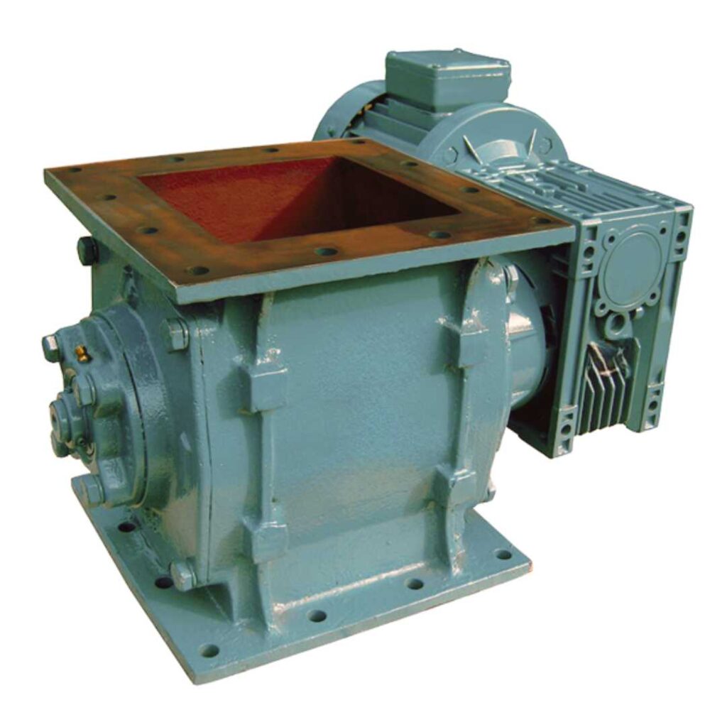
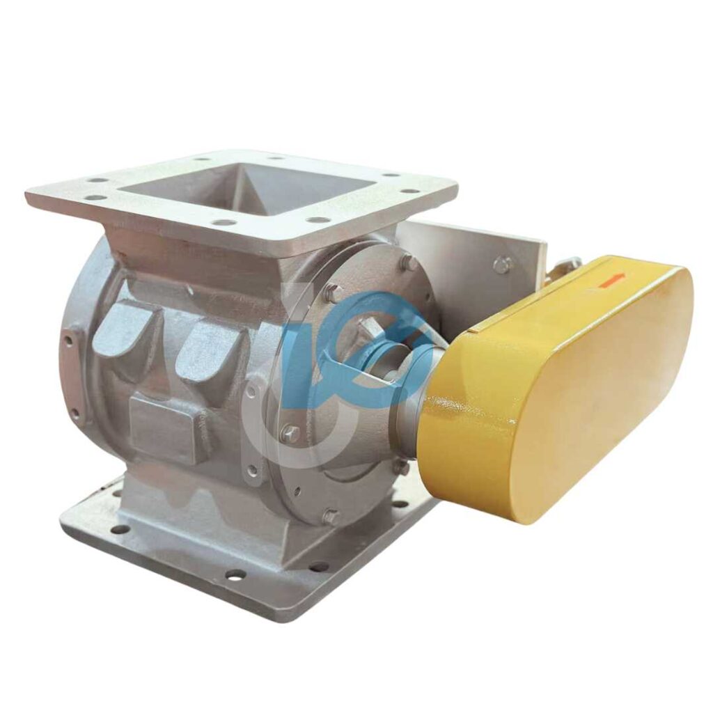
This is the “classic” rotary valve you’ll find in many plants. Material enters from the top and drops directly into the cavity of the rotor, which then rotates and discharges it downward into the next stage of the process.

  • Where it’s used: Perfect for handling free-flowing powders, grains, and pellets.
  • Why it’s popular: Simple, reliable, and cost-effective, the direct gravity-assisted flow makes it less prone to clogging.
  • Key advantage: Works well in applications where air leakage control is not extremely critical, like feeding dust collectors or silos.

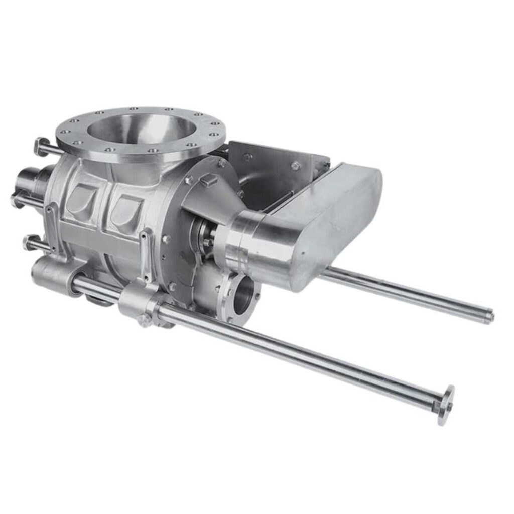
This type is designed with pneumatic conveying in mind. Instead of simply dropping through, the material is discharged directly into a pressurized conveying line with the help of air or gas.

  • Where it’s used: Perfect for handling free-flowing powders, grains, and pellets.
  • Why it’s popular: Reduces product build-up inside the valve and ensures a smooth transition into the pipeline.
  • Key advantage:  Particularly effective for cohesive or sticky powders, where a drop-through design might struggle with blockages.


3. Easy-Clean Rotary Valve

Hygiene-sensitive industries, like food processing and pharmaceuticals, can’t afford contamination or product cross-over. That’s where easy-clean designs shine.

easy-clean-rotary-valve
  • Where it’s used: Food, dairy, nutraceuticals, and pharmaceutical manufacturing.
  • Why is it needed: Regulations demand frequent cleaning and inspection.
  • Key advantage: These valves are built with quick-release mechanisms that allow the rotor to be removed without dismantling the entire unit, saving precious time during product changeovers.


4. High-Temperature or Heavy-Duty Valves

Not all materials are gentle. Some are abrasive, corrosive, or processed at high temperatures. Heavy-duty rotary valves are designed to withstand these punishing conditions.

  • Where it’s used: Industries like cement, minerals, steel, power plants, and chemicals.
  • Why it’s important: Standard valves would wear out too quickly under such stress.
  • Key advantages: Built with special alloys, wear-resistant coatings, and reinforced housings to resist abrasion, erosion, and thermal expansion.


Challenges Caused by Improper Rotary Valve Design

Let’s be real if the rotary valve isn’t designed correctly, you’ll know it. Some common headaches include:

  • Excessive Air Leakage: leading to poor system performance and higher energy costs.
  • Material Jamming or Build-Up: especially if you’re handling sticky or hygroscopic powders.
  • Excessive Wear: When abrasive materials erode the rotor tips or housing too quickly.
  • Inconsistent Feed Rates: disrupting downstream processes and product quality.
  • Difficult Maintenance: valves that are tough to clean or disassemble lead to longer downtimes.

All these stems from one root cause: not considering key design factors early on.


Key Factors to be Considered for Rotary Valve Design

1. Material Characteristics

  • Is your material free-flowing, abrasive, or sticky?
  • Powders like flour behave very differently compared to materials like silica or polymer pellets.
  • Choosing the wrong clearances, coatings, or rotor type can quickly damage your valve.

2. Operating Pressure and Temperature

  • Rotary valves act as “airlocks” between pressure zones.
  • If the design doesn’t match your pressure or temperature range, you’ll face leakage or thermal expansion issues.
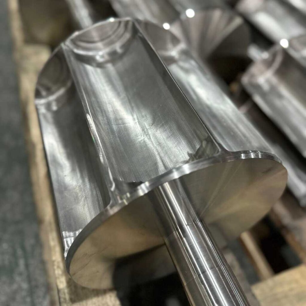
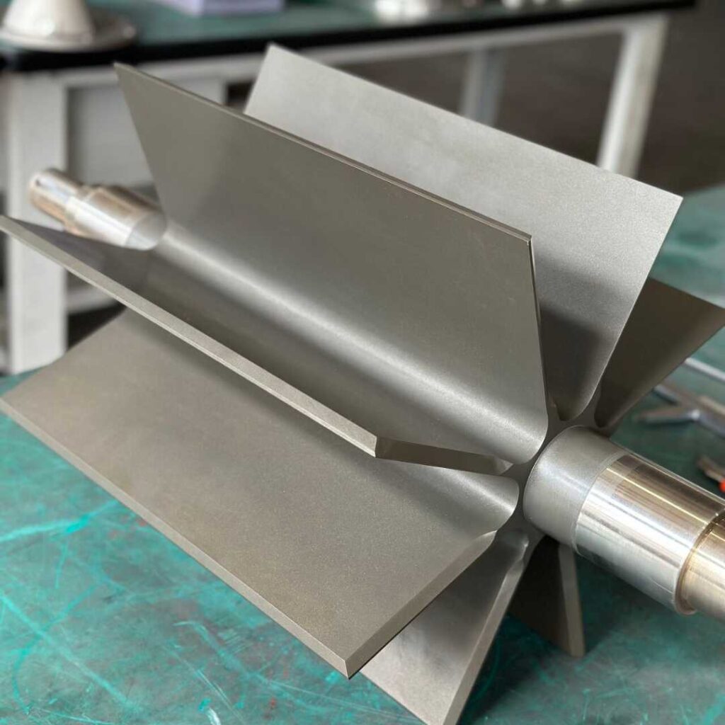
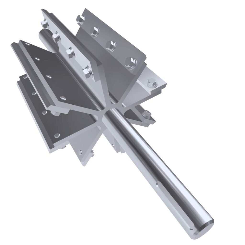
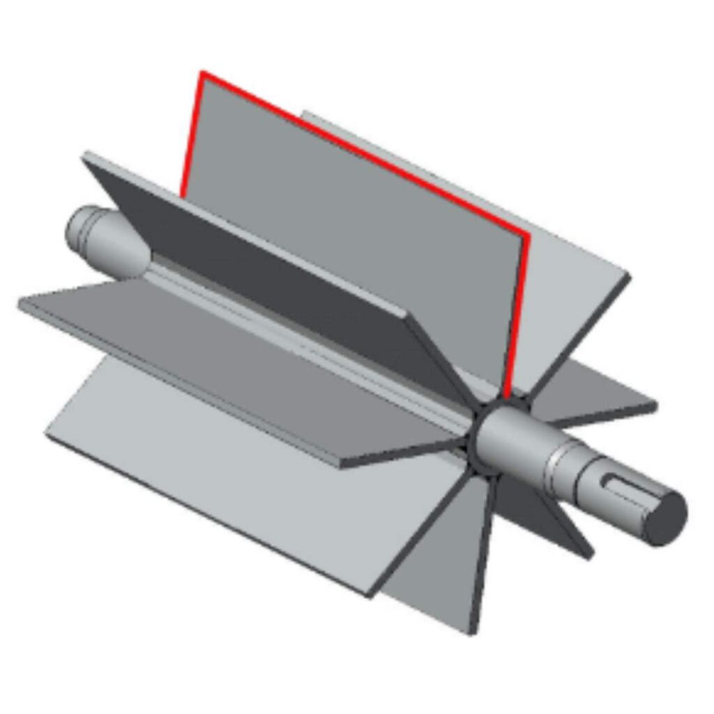
3. Rotor Design

  • Number of vanes, type of tips (metal, rubber, or composite), rotor geometry and the gap clearance all play a role.
  • It’s about finding the right balance for your process.

4. Construction Material & Coatings

  • Cast iron, stainless steel, or special alloys each have its pros and cons.
  • For abrasive products, hardened or coated surfaces extend life.
  • For food and pharma, stainless steel with a smooth finish is a must.

5. Capacity & Throughput

  • Oversized valves lead to air leakage; undersized ones choke your system.
  • Calculating the correct throughput based on bulk density and rotor volume is key.

6. Maintenance & Cleanability

  • Does your process need frequent cleaning? Go for easy-clean or quick-release designs.
  • Poorly accessible valves increase downtime and risk of contamination.
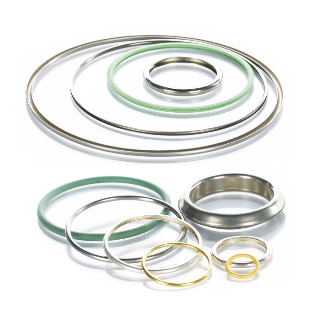
7. Sealing System

  • Shaft seals must be chosen carefully; stuffing box, mechanical seals, or air purged seals depending on your application.
  • The right sealing prevents product leakage and protects bearings.

8. Energy Efficiency

  • A valve with poor clearances or wrong design can make your blower/compressor work harder.
  • Energy-efficient designs save costs in the long run.

A rotary airlock valve may look like a simple device, but its design can make or break your system’s performance. By carefully considering material properties, operating conditions, rotor design, sealing, and cleanability, you can ensure your valve runs reliably and efficiently for years.

Remember, the cheapest option isn’t always the best. A well-designed valve reduces downtime, maintenance costs, and headaches leaving you free to focus on production instead of repairs.

So next time you’re specifying a rotary valve, take a step back and ask: Is this design really right for my process? That one question can save you a lot of trouble later.

Introduction to Rotary Airlock Valve

Introduction to Rotary Airlock Valve (RAV)

Pneumatic conveying systems play a vital role in efficiently transporting materials across various industries. A key player in these systems is the rotary airlock valve. If you’re unfamiliar with what rotary airlock valves are, how they operate, the various types available, and their typical applications, we’ve got you covered. This article aims to provide all the essential information about rotary airlock valves, commonly referred to as RAV, so you can gain a comprehensive understanding of their functionality and importance in material transport systems.


What is Rotary Airlock Valve?

Rotary airlocks go by various names like rotary locks, rotary feeders, or simply “airlocks.” Despite the different terms, their main job stays the same. They make it easy to move dry, free-flowing bulk solids—like powders, granules, pellets, nuggets, dust, and crystals—from a storage bin, storage silo, hopper, cyclone, or receiver through a pneumatic conveying system to the next step in the manufacturing process. These valves are essential for keeping material handling and pneumatic conveying systems efficient and reliable. They ensure a controlled and uninterrupted flow of bulk materials, prevent air leakage, and maintain system pressure.


How Does a Rotary Airlock Valve Work?

A rotary airlock is comprised of several key components, including a casted outer housing, a fabricated multi-vane rotor and shaft, endplates, a drive, shaft packing seals, and bearings.

Here’s a breakdown of its operation:

❖ Functionality:

  • When activated, the vanes of the rotary airlock rotate within the housing, resembling the movement of a revolving door. The primary objective is to facilitate the controlled movement of materials while preventing pressure loss, much like a revolving door manages the flow of people while preserving the indoor environment.

❖ Rotor Pocket:

  • The space between the rotating vanes forms the rotor pocket. This is where incoming material enters from the top opening and stays before being pushed out through the lower opening, continuing its journey through the pneumatic lines.

❖ Pressure Control:

  • The tight clearance between the vanes and housing minimizes pressure loss in the system. This is crucial, especially when dealing with varying pressures between bins, silos, hoppers, and the adjacent operation. Placing airlocks at the beginning of a pressure system or at the end of a vacuum system helps maintain optimal pressure conditions.


Types of Rotary Airlock Valves

Rotary airlock valves come in various types, each designed to suit specific applications and operational requirements. Here are some common types of rotary airlock valves:

Fall-Through Rotary Airlock Valve:​

Blow-Through Rotary Airlock Valve:

Standard Duty Rotary Airlock Valve:

Heavy Duty Rotary Airlock Valve:

Quick-Clean Rotary Airlock Valve:

Dust Collector (Dust Disposal) Rotary Airlock Valve:


Seals used in Rotary Airlock Valve

Rotary airlock valves use various types of seals to maintain an airtight or dust-tight seal between different pressure zones in material handling and processing systems. Here are common types of seals used in rotary airlock valves:

Flexible Rubber Seals:

Neoprene Seals:

Nitrile (Buna-N) Seals:

Polyurethane Seals:

Metal-to-Metal Seals:

The selection of a specific seal depends on the specific requirements of the application, including the type of material being handled, the operating temperature and pressure, and the desired level of sealing effectiveness. Regular maintenance and monitoring of seals are important to ensure the continued reliability and performance of rotary airlock valves.


Types of Rotors used in Rotary Airlock Valve

There are several types of rotors used in rotary airlock valves, each designed for specific applications. The common types of rotors include:

Closed-End Rotor

A closed-end rotor has solid ends on both sides. It is suitable for handling non-abrasive materials and applications where a tight seal is essential to prevent air leakage between different pressure zones.

Open-End Rotor

An open-end rotor has one side open, allowing for easier material entry and discharge. It is commonly used in applications where material characteristics or system requirements permit some air leakage.

Dust-Collector Rotor

This type of rotor is designed with large pockets to collect and discharge fine dust or powders. It helps prevent material build-up and reduces the risk of rotor jamming, making it suitable for applications with dusty materials.

Shallow-Pocket Rotor:

Shallow-pocket rotors are designed with smaller pocket depths. They are often used for applications involving sticky or tacky materials to prevent material build-up within the pockets.

Adjustable-Tip Rotor:

Adjustable-tip rotors allow the rotor tips to be adjusted to maintain the proper clearance between the rotor and the housing. This feature is useful for fine-tuning the valve’s performance and addressing wear over time.

Rigid Pocket Rotor

Rigid pocket rotors have reinforced pockets, making them suitable for handling abrasive materials. They provide increased durability and resistance to wear.


Materials used for manufacturing Rotary Airlock Valve

Rotary airlock valves are crucial components in pneumatic conveying systems, and their construction materials are chosen based on factors such as the type of material being handled, the system’s operating conditions, and considerations for wear resistance. Common materials used for manufacturing rotary airlock valves include:

Carbon Steel:

Carbon steel is often used for the construction of rotary airlock valve components, including the endplates and rotor. It offers strength and durability in various operating environments.

Cast Iron:

Cast iron is a common material for rotary airlock valve housings and endplates. It provides good strength and wear resistance. Gray iron and ductile iron are variations of cast iron used in different applications.

Stainless Steel:

Stainless steel is chosen for applications where corrosion resistance is critical. Types such as 304 and 316 stainless steel are commonly used to prevent rust and corrosion, making them suitable for handling corrosive materials or operating in harsh environments.

Aluminum:

Aluminum is chosen for applications where weight is a significant consideration. It is lighter than steel, making it suitable for certain industries or applications with specific requirements.

Hardened Steel or Tool Steel:

Hardened or tool steel may be used for rotors, especially in applications where abrasion resistance is crucial. Hardened steel helps extend the life of the rotor in handling abrasive materials.

Ceramic Coatings:

Some rotary airlock valves may have ceramic coatings or inserts to enhance wear resistance, particularly when handling abrasive materials. Ceramic materials provide excellent resistance to abrasion.

Specialized Coatings:

Various specialized coatings, such as tungsten carbide, may be applied to critical wear areas to improve durability and extend the life of the rotary airlock valve in challenging conditions.

Polymer and Composite Materials:​

In certain applications, polymer or composite materials may be used for specific components to provide chemical resistance or reduce wear. This can include polymer housings or coatings.


Factors to be considered for selection of Rotary Airlock Valve

Material to be conveyed

When choosing a rotary airlock, consider the material characteristics such as abrasiveness, moisture content, and particle size. Selection factors include using hard-faced components for abrasives and ensuring a tight seal for moist materials to prevent air entry and drying. The rotary airlock should match the specific requirements of the material and its flow characteristics.

Flow Rate

For effective pneumatic conveying systems, choose a rotary airlock that matches the material’s flow rate. Avoid bottlenecks by ensuring the rotor’s size and speed align with the flow rate. An appropriately sized rotary airlock enhances energy efficiency and reduces maintenance costs.

Pressure Drop

When selecting a rotary airlock, be mindful of pressure drop—the difference between inlet and outlet pressures. High pressure drop reduces system efficiency and increases energy costs. To minimize this, choose a rotary airlock with a tight seal and a rotor correctly sized for the flow rate.

Type of Pneumatic Conveying System

Selecting the right rotary airlock depends on the type of pneumatic conveying system. Dilute phase systems benefit from flow-through rotary airlocks (drop-through), suitable for materials like grain, coffee beans, polymer granules, etc. Materials like flour, cocoa powder, chemical powders work well with blow-through rotary airlocks. Matching the rotary airlock to the conveying system ensures optimal performance.

Maintenance and Repair

Go for designs that provide convenient access to the rotor and vanes. Look for rotary airlocks with replaceable parts to minimize downtime and lower maintenance costs.