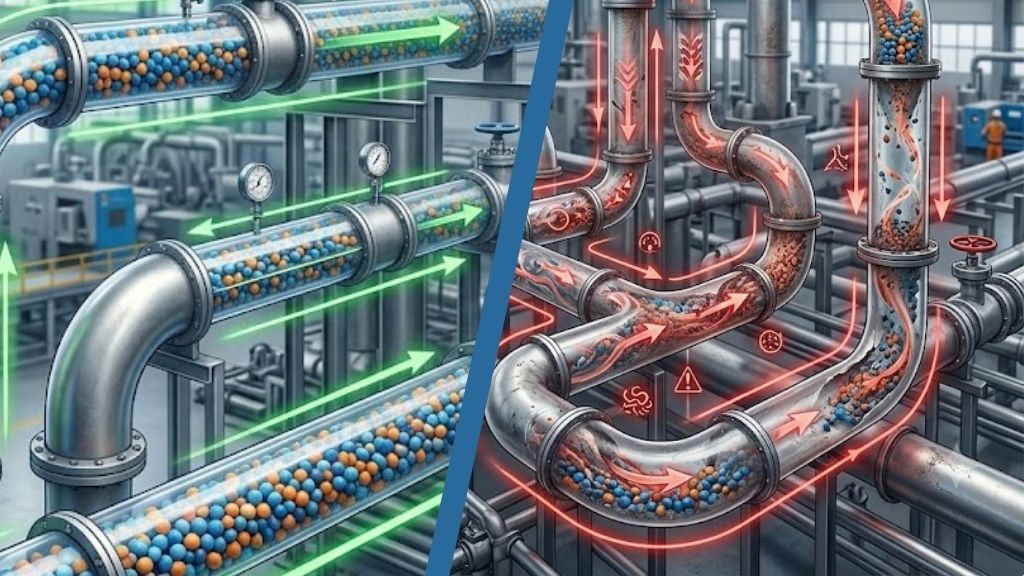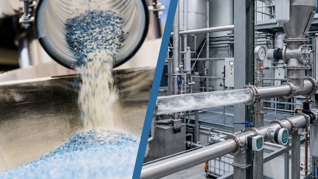

Why Pneumatic Conveying Lines Get Blocked & How to Prevent It
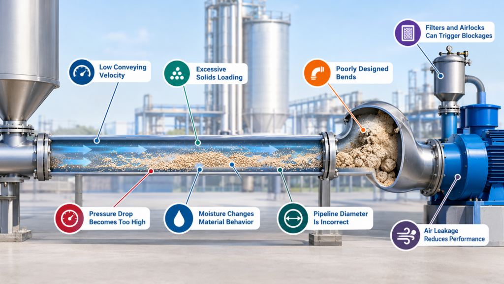
For material to move reliably, the conveying air must generate sufficient drag to transport the particles through the pipeline. If the available conveying force becomes insufficient, particles begin to settle.
This is particularly important in horizontal sections, bends, reducers, and other areas where pressure losses are higher.
The process can become self-reinforcing:
Lower airflow → particle settling → increased resistance → higher pressure drop → further reduction in conveying performance → blockage.
Therefore, the objective should not simply be to clear a plugged line. The real engineering objective is to identify what caused the system to leave its stable conveying envelope.
1. Low Conveying Velocity
One of the most common causes of blockage is insufficient air velocity.
Every material has a range of conveying conditions below which particles can begin to settle. In dilute-phase conveying, this is commonly discussed in terms of saltation velocity – the approximate condition at which particles begin to deposit rather than remain effectively transported.
The required velocity depends on:
- Particle size and density
- Particle shape
- Bulk density
- Moisture
- Cohesiveness
- Solids loading
- Pipeline diameter
- Conveying pressure
- Q = volumetric airflow
- A = pipeline cross-sectional area
- V = average air velocity
2. Excessive Solids Loading
If too much material is introduced into the pipeline without sufficient conveying air, the solids-to-air ratio increases. The air stream may no longer have enough momentum and drag to maintain stable transport.
This can happen when:
- Feed rate is increased
- A rotary airlock is oversized
- Material bulk density changes
- A feeder operates above its design rate
- Material enters the line in slugs
A system designed for a particular solids loading should therefore not be operated continuously beyond that envelope simply to increase production.
A stable 8 tonnes/hour can be more productive over a year than an unstable 10 tonnes/hour system that repeatedly blocks.
3. Pressure Drop Becomes Too High
For gas flow through a straight pipe, a useful engineering relationship is the Darcy-Weisbach equation:

where:
- ΔP = pressure loss
- f = friction factor
- L = pipe length
- D = pipe diameter
- ρ = gas density
- V = gas velocity
4. Poorly Designed Bends
When particles change direction, their inertia causes them to resist the change in motion. Larger or denser particles can impact the outer wall of the bend, while cohesive or fragile materials may accumulate or degrade.
Poor bend design can therefore produce:
- Material deposition
- Erosion
- Product degradation
- Excessive pressure loss
- Repeated plugging
5. Moisture Changes Material Behavior
A material that flows freely when dry can become cohesive when exposed to humidity. Fine particles may agglomerate, stick to the pipe wall, or form deposits.
Moisture can alter:
- Bulk density
- Cohesiveness
- Flowability
- Particle size
- Angle of repose
Therefore, the conveying system may effectively be handling a different material from the one used during its original design.
Prevention: Control material moisture, prevent condensation, maintain appropriate conveying-air conditions, and keep moisture-sensitive materials properly sealed.
6. Pipeline Diameter Is Incorrect
An undersized pipe can produce excessive pressure drop and high particle velocity. An oversized pipe can reduce velocity below the stable conveying range if airflow is not increased.
This is another application of the continuity relationship:
V = Q / A
Increasing diameter increases area, so the same airflow produces a lower velocity.
The largest possible pipe is therefore not necessarily the best pipe.
Good design balances velocity, pressure drop, energy consumption, wear, and material handling requirements.
7. Air Leakage Reduces Conveying Performance
The result may be:
Designed airflow ≠ Actual conveying airflow
This is especially important in systems operating close to their minimum conveying conditions.
Routine inspection of joints and flexible connections, combined with airflow and pressure monitoring, can identify developing problems before they become blockages.
8. Filters and Airlocks Can Trigger Blockages
A dirty filter increases resistance. A worn rotary airlock can allow excessive air leakage. A malfunctioning feeder can introduce material inconsistently.
These failures can change the system’s pressure and airflow balance.
Pressure-drop monitoring is therefore valuable.
A gradual increase in differential pressure across a filter may indicate fouling. An unexpected change in conveying-line pressure may indicate restriction, leakage, or altered material loading.
This turns instrumentation into an early-warning system rather than simply a method of displaying operating conditions.