Indpro Logo

Indpro
Typically replies within an hour

Indpro
"Hello!👋

How can I help you today with your bulk material handling needs?"
×
Chat with Us

How to Choosing the Right Industrial Dust Control System

Choosing the Right Industrial Dust Control System :
A Comprehensive 10 Step Process

When it comes to maintaining a healthy and safe working environment in a process industrial setting, the implementation of an appropriate dust collection system plays a crucial role. Industrial dust can pose serious health risks for workers and equipment if left unmanaged. In this blog, we will explore the factors that should be considered when choosing an industrial dust control system. By understanding the specific requirements of your application, the characteristics of different types of dust, and the various aspects of dust control systems, you can make an informed decision that ensures the well-being of your workforce and the longevity of your equipment.


1. What is your application?

Before diving into the intricacies of dust control systems, it is important to assess the specific needs of your application. Different industries have different levels of dust generation, types of dust, and environmental considerations. Whether you work in mining, woodworking, or manufacturing, understanding your application will help you determine the appropriate dust control solution. For example, a chemical industry facility may require a dust control system with high filtration capabilities for fine particles released during material handling, blending, or packaging processes, to maintain a clean and safe atmosphere within the facility. The emphasis on product recovery and minimization of emission levels could be crucial. On the other hand, in pharmaceutical industries, the dust control system may require a stringent clean-in-place arrangement to ensure the equipment is clean during batch changeovers.


2. What is dust and what characteristics do different types of dust have?

To effectively manage dust, it is essential to understand its composition and characteristics. Dust particles vary in size, shape, and chemical composition, which affects their behavior and potential hazards. For instance, silica dust, commonly found in construction and mining industries, is known to cause respiratory health issues. By identifying the specific characteristics of dust generated in your application, you can choose a dust control system that effectively captures and manages those particles. Some dusts are sticky in nature & require special filter element cleaning systems where a simple ‘pulse-jet’ would not suffice. Analyzing the dust properties is essential for selecting the right system configuration.


3. Size of dust collector

The size of the dust collector is an important factor to consider to ensure optimal dust control. A dust collector that is too small may not have sufficient capacity to handle the volume of dust generated, leading to inefficient performance and potential safety concerns. On the other hand, an oversized dust collector may result in unnecessary energy consumption and increased upfront costs. By accurately assessing the dust generation rate in your application, calculating the air volume in cubic feet per minute (CFM) is essential for determining the appropriate size of the dust collector.


4. Dust generation rate per cubic feet

To properly size the dust control system, it is crucial to understand the rate at which dust is generated in your facility. By measuring the dust generation rate per cubic feet, you can estimate the overall dust generation and select a dust control system that can handle the expected flow. This data also helps in determining the frequency of maintenance and filter replacements, ensuring the consistency and efficiency of your dust control system.


5. Setup location of the dust collector

The placement of the dust collector plays a significant role in its effectiveness. A well-thought-out location ensures optimal collection of dust particles and minimizes the dispersion of airborne contaminants within the facility. Additionally, considering access for maintenance and ease of filter replacement is crucial when selecting the setup location for the dust collector. By strategically placing the dust collector in areas where dust is generated or concentrated, you can minimize the risk of dust accumulation and improve the overall performance of the system. A strategic placement also optimizes the routing of the dust collection ducting.


6. Indoor dust collector or outdoor dust collector

The decision to opt for an indoor or outdoor dust collector depends on various factors, such as available space, environmental conditions, and specific industry requirements. Indoor dust collectors are typically used when product recovery is important to the process and space is not a constraint. On the other hand, outdoor dust collectors are suitable for applications where large volumes of dust are generated or where space is a constraint. By evaluating the specific needs of your facility, you can determine whether an indoor or outdoor dust collector is the right choice for your dust control needs.


7. Installation requirements

To ensure the proper functioning of the dust control system, it is essential to consider the installation requirements. This includes evaluating the available utilities, such as electricity and compressed air, which are necessary for the operation of the system. Additionally, understanding the space requirements, such as the height, width, and clearance, will assist in selecting a dust collector that can be easily accommodated in your facility. Evaluating the installation requirements will help you avoid any potential challenges or delays during the setup process.


8. Understand the working principles of dust collectors based on their types

Different types of dust collectors utilize varying mechanisms to capture and separate dust particles from the air. It is important to understand the working principles of dust collectors to select a system that aligns with your needs. Baghouses filter, cartridge filter, cyclone separators, Pulse jet filter, electrostatic precipitators and wet scrubbers are some of the common types of dust collectors. Every category comes with its unique set of advantages and limitations. By gaining a comprehensive understanding of these mechanisms, you can choose a dust collector that best suits your application and maximizes dust control efficiency.


9. Value for money

While cost is an important consideration, it should not be the sole deciding factor when selecting a dust control system. Evaluating the value for money involves considering factors such as initial cost, maintenance requirements, energy efficiency, and lifespan of the equipment. A dust control system that may have a higher upfront cost but offers better filtration efficiency and longer lifespan can result in cost savings in the long run. Balancing the initial investment with long-term benefits will help you make a financially sound decision.


10. What kinds of support do you expect from your dust collector after\-sales service?

The after-sales service and support provided by the dust collector manufacturer should not be overlooked. When selecting a dust control system, consider the level of technical support, availability of replacement parts, and warranty offered by the manufacturer. A reliable after-sales service ensures that any issues or concerns with the dust control system can be promptly addressed, minimizing downtime, and maximizing the performance of your dust control solution.

Choosing the right dust control system for your industrial application is crucial for maintaining a safe and healthy work environment. By considering factors such as your specific application, dust characteristics, sizing requirements, setup location, type of dust collector, installation requirements, working principles, value for money, and after-sales support, you can make a well-informed choice that aligns with your specific requirements. Remember, investing in an effective dust control system not only protects the well-being of your workforce but also ensures the longevity and productivity of your equipment. So, take the time to evaluate these factors and choose a dust control system that will safeguard both your employees and your business.

Introduction to Rotary Airlock Valve

Introduction to Rotary Airlock Valve (RAV)

Pneumatic conveying systems play a vital role in efficiently transporting materials across various industries. A key player in these systems is the rotary airlock valve. If you’re unfamiliar with what rotary airlock valves are, how they operate, the various types available, and their typical applications, we’ve got you covered. This article aims to provide all the essential information about rotary airlock valves, commonly referred to as RAV, so you can gain a comprehensive understanding of their functionality and importance in material transport systems.


What is Rotary Airlock Valve?

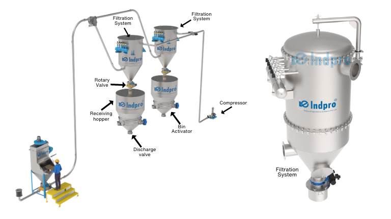
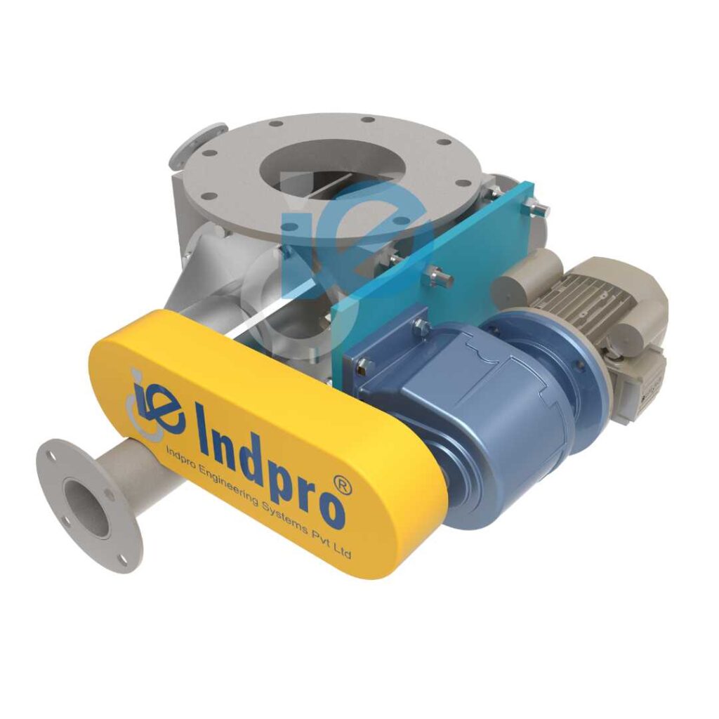
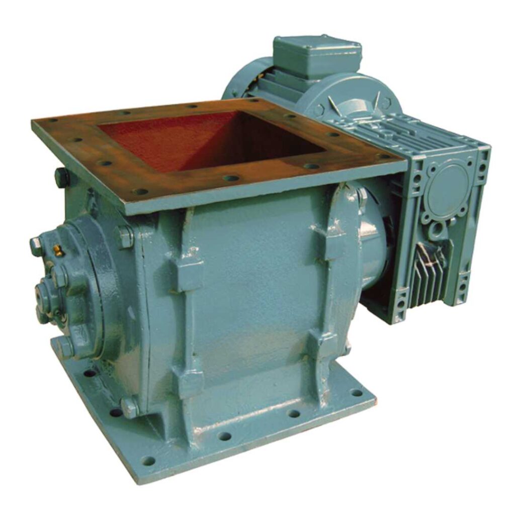
Rotary airlocks go by various names like rotary locks, rotary feeders, or simply “airlocks.” Despite the different terms, their main job stays the same. They make it easy to move dry, free-flowing bulk solids—like powders, granules, pellets, nuggets, dust, and crystals—from a storage bin, storage silo, hopper, cyclone, or receiver through a pneumatic conveying system to the next step in the manufacturing process. These valves are essential for keeping material handling and pneumatic conveying systems efficient and reliable. They ensure a controlled and uninterrupted flow of bulk materials, prevent air leakage, and maintain system pressure.


How Does a Rotary Airlock Valve Work?

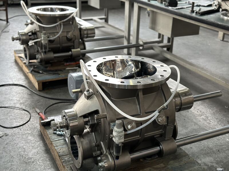
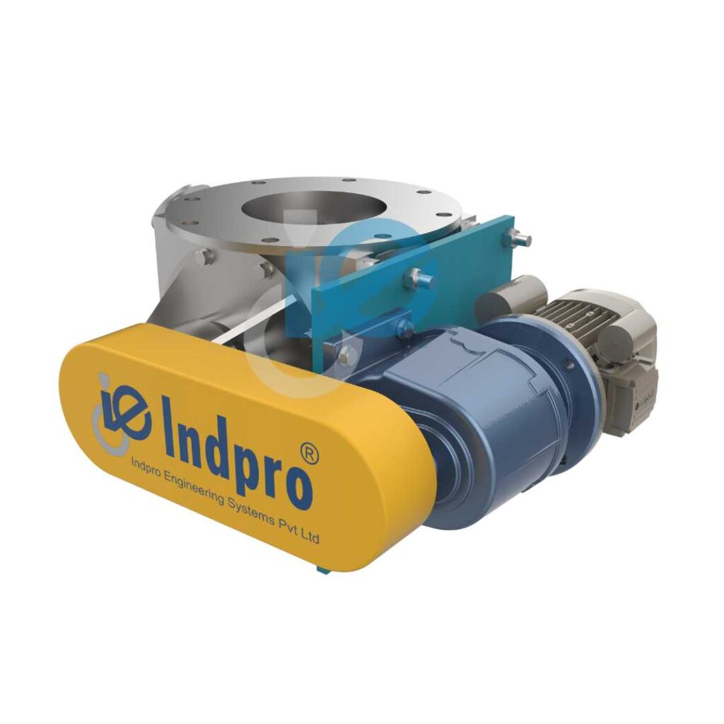
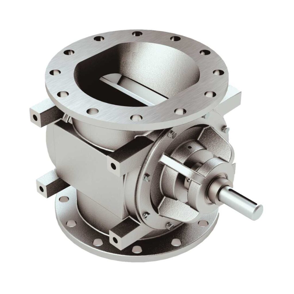
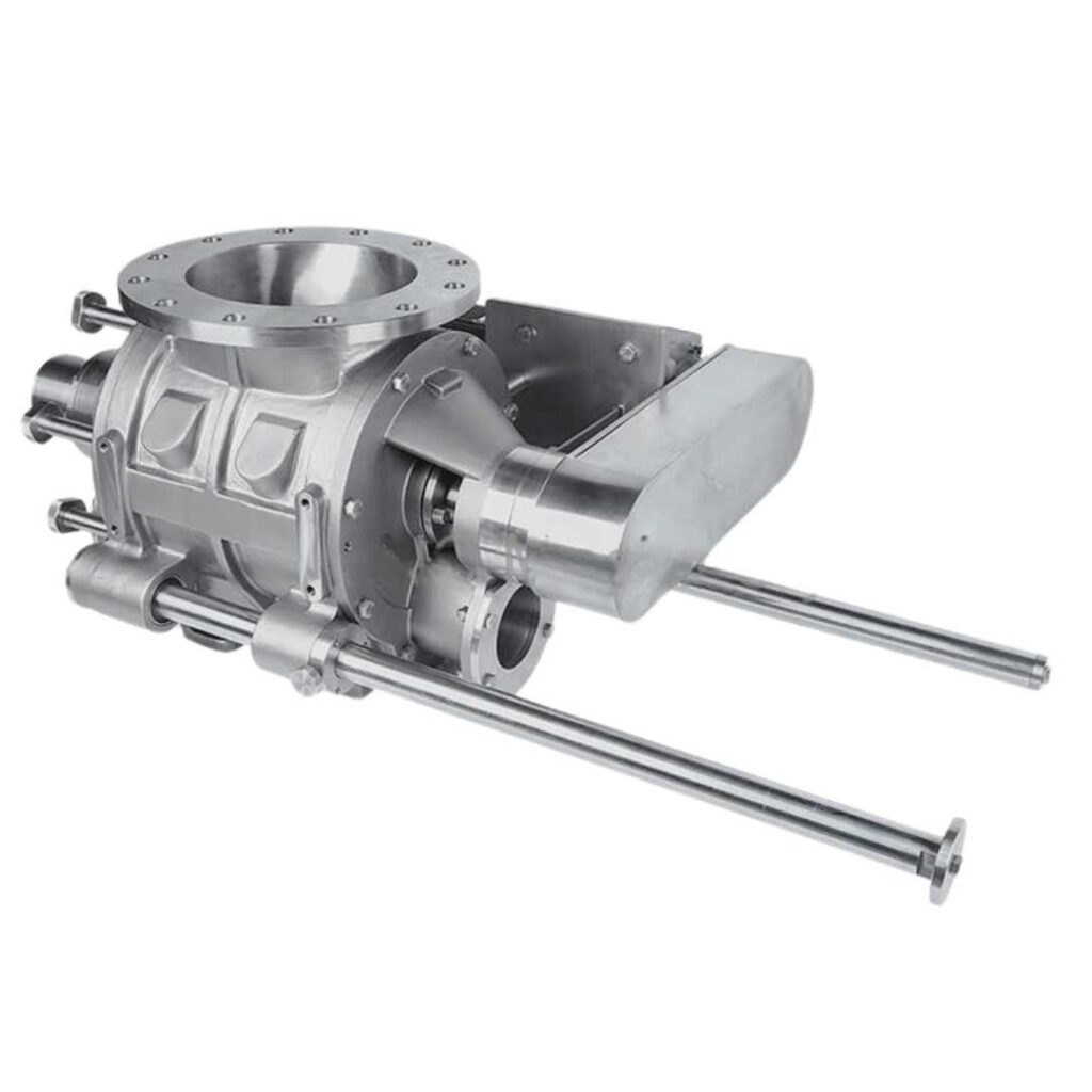
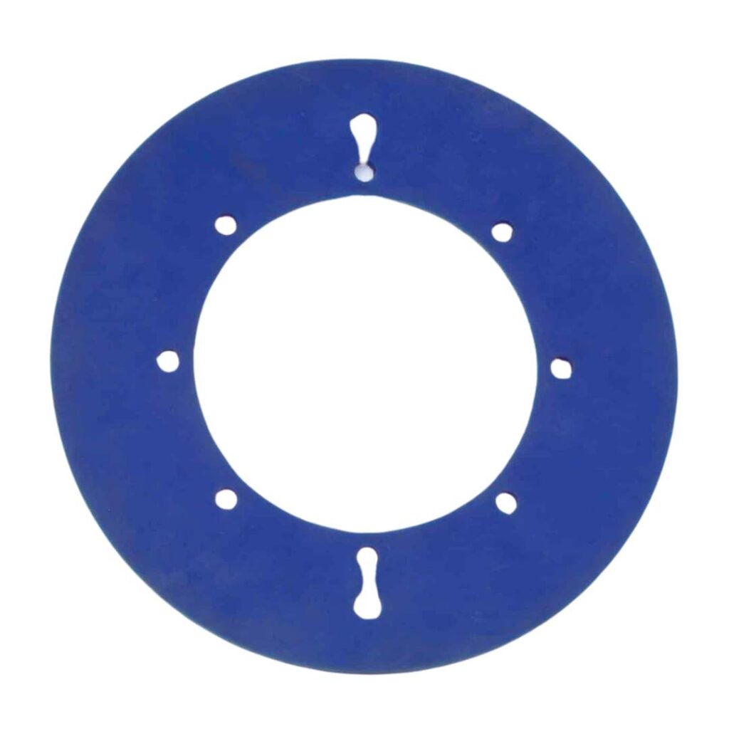
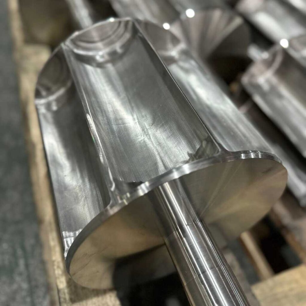
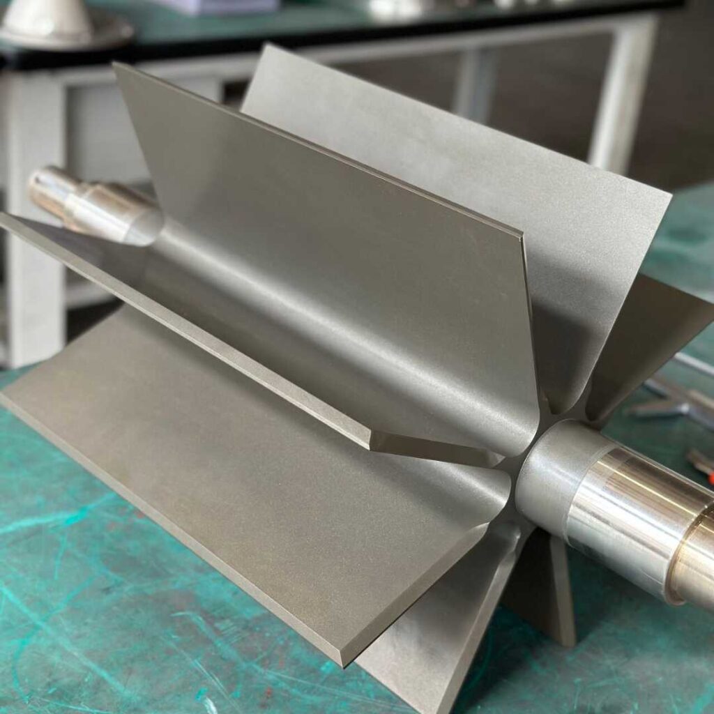
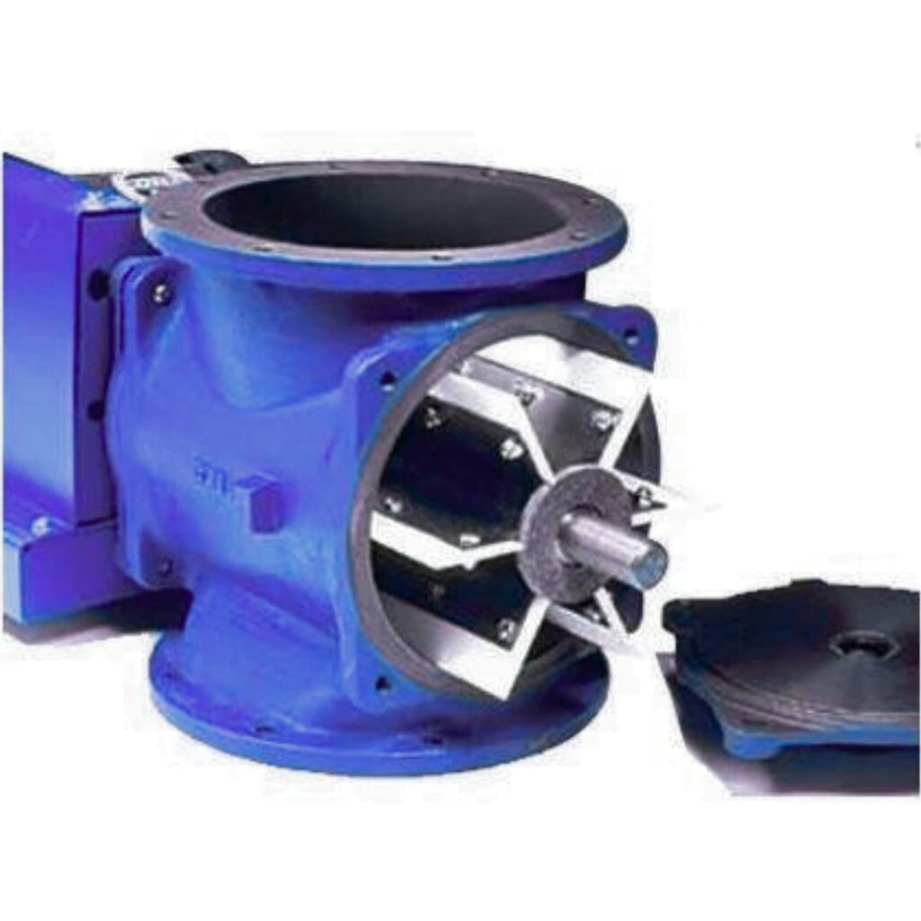
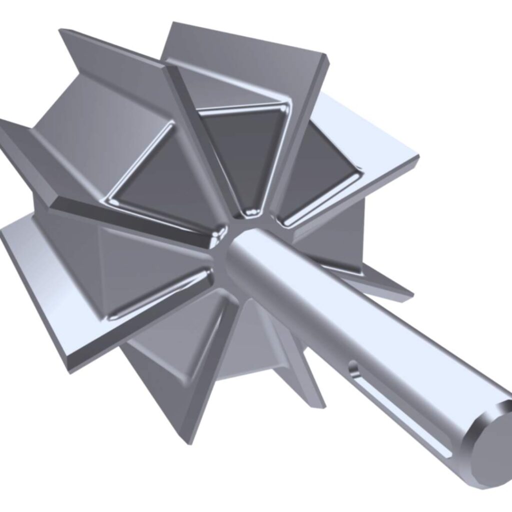
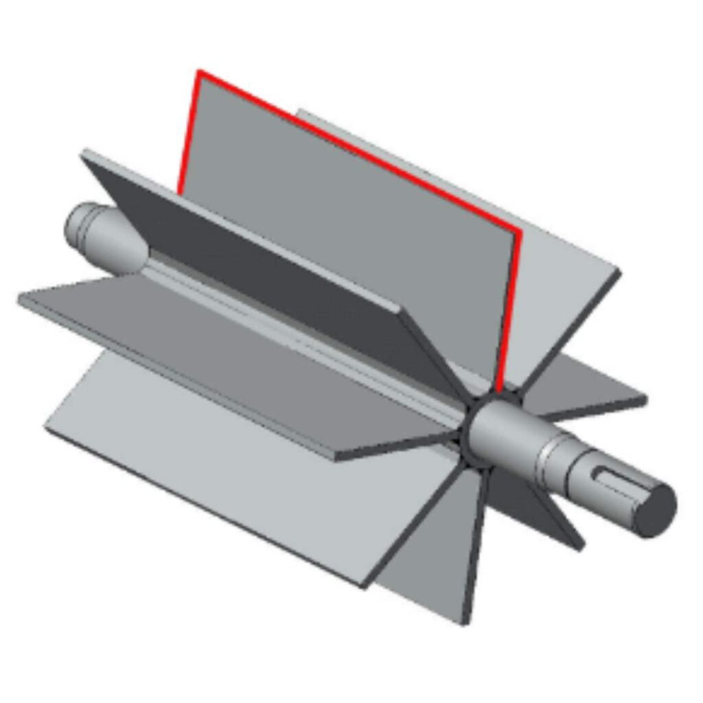
A rotary airlock is comprised of several key components, including a casted outer housing, a fabricated multi-vane rotor and shaft, endplates, a drive, shaft packing seals, and bearings.

Here’s a breakdown of its operation:

❖ Functionality:

  • When activated, the vanes of the rotary airlock rotate within the housing, resembling the movement of a revolving door. The primary objective is to facilitate the controlled movement of materials while preventing pressure loss, much like a revolving door manages the flow of people while preserving the indoor environment.

❖ Rotor Pocket:

  • The space between the rotating vanes forms the rotor pocket. This is where incoming material enters from the top opening and stays before being pushed out through the lower opening, continuing its journey through the pneumatic lines.

❖ Pressure Control:

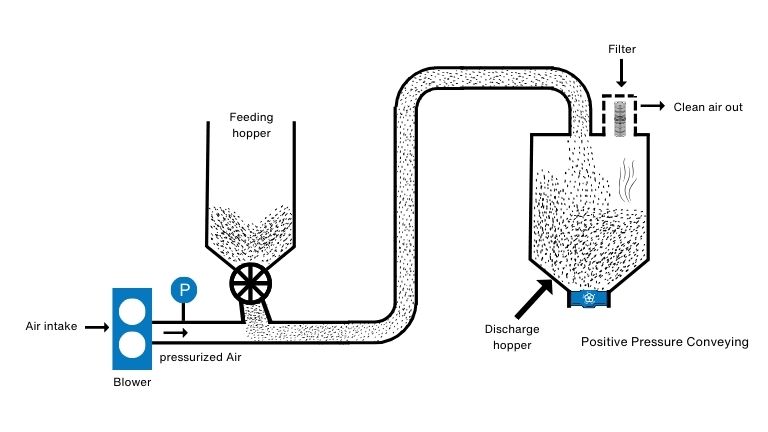
  • The tight clearance between the vanes and housing minimizes pressure loss in the system. This is crucial, especially when dealing with varying pressures between bins, silos, hoppers, and the adjacent operation. Placing airlocks at the beginning of a pressure system or at the end of a vacuum system helps maintain optimal pressure conditions.


Types of Rotary Airlock Valves

Rotary airlock valves come in various types, each designed to suit specific applications and operational requirements. Here are some common types of rotary airlock valves:

Fall-Through Rotary Airlock Valve:​

Blow-Through Rotary Airlock Valve:

Standard Duty Rotary Airlock Valve:

Heavy Duty Rotary Airlock Valve:

Quick-Clean Rotary Airlock Valve:

Dust Collector (Dust Disposal) Rotary Airlock Valve:


Seals used in Rotary Airlock Valve

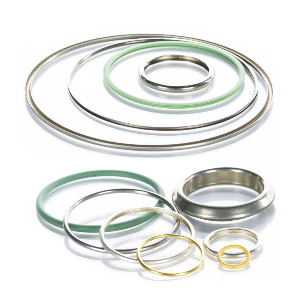
Rotary airlock valves use various types of seals to maintain an airtight or dust-tight seal between different pressure zones in material handling and processing systems. Here are common types of seals used in rotary airlock valves:

Flexible Rubber Seals:

Neoprene Seals:

Nitrile (Buna-N) Seals:

Polyurethane Seals:

Metal-to-Metal Seals:

The selection of a specific seal depends on the specific requirements of the application, including the type of material being handled, the operating temperature and pressure, and the desired level of sealing effectiveness. Regular maintenance and monitoring of seals are important to ensure the continued reliability and performance of rotary airlock valves.


Types of Rotors used in Rotary Airlock Valve

There are several types of rotors used in rotary airlock valves, each designed for specific applications. The common types of rotors include:

Closed-End Rotor

A closed-end rotor has solid ends on both sides. It is suitable for handling non-abrasive materials and applications where a tight seal is essential to prevent air leakage between different pressure zones.

Open-End Rotor

An open-end rotor has one side open, allowing for easier material entry and discharge. It is commonly used in applications where material characteristics or system requirements permit some air leakage.

Dust-Collector Rotor

This type of rotor is designed with large pockets to collect and discharge fine dust or powders. It helps prevent material build-up and reduces the risk of rotor jamming, making it suitable for applications with dusty materials.

Shallow-Pocket Rotor:

Shallow-pocket rotors are designed with smaller pocket depths. They are often used for applications involving sticky or tacky materials to prevent material build-up within the pockets.

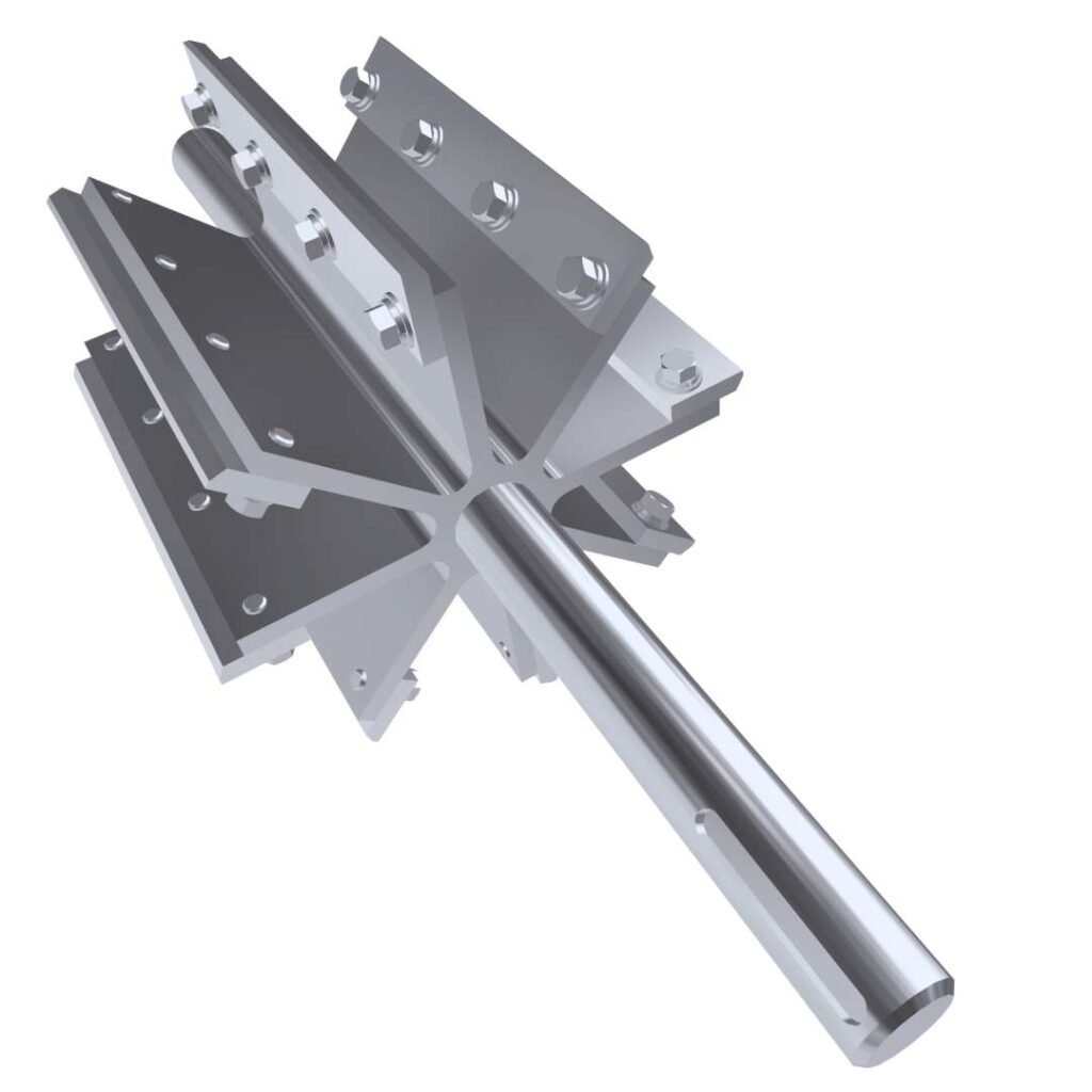
Adjustable-Tip Rotor:

Adjustable-tip rotors allow the rotor tips to be adjusted to maintain the proper clearance between the rotor and the housing. This feature is useful for fine-tuning the valve’s performance and addressing wear over time.

Rigid Pocket Rotor

Rigid pocket rotors have reinforced pockets, making them suitable for handling abrasive materials. They provide increased durability and resistance to wear.


Materials used for manufacturing Rotary Airlock Valve

Rotary airlock valves are crucial components in pneumatic conveying systems, and their construction materials are chosen based on factors such as the type of material being handled, the system’s operating conditions, and considerations for wear resistance. Common materials used for manufacturing rotary airlock valves include:

Carbon Steel:

Carbon steel is often used for the construction of rotary airlock valve components, including the endplates and rotor. It offers strength and durability in various operating environments.

Cast Iron:

Cast iron is a common material for rotary airlock valve housings and endplates. It provides good strength and wear resistance. Gray iron and ductile iron are variations of cast iron used in different applications.

Stainless Steel:

Stainless steel is chosen for applications where corrosion resistance is critical. Types such as 304 and 316 stainless steel are commonly used to prevent rust and corrosion, making them suitable for handling corrosive materials or operating in harsh environments.

Aluminum:

Aluminum is chosen for applications where weight is a significant consideration. It is lighter than steel, making it suitable for certain industries or applications with specific requirements.

Hardened Steel or Tool Steel:

Hardened or tool steel may be used for rotors, especially in applications where abrasion resistance is crucial. Hardened steel helps extend the life of the rotor in handling abrasive materials.

Ceramic Coatings:

Some rotary airlock valves may have ceramic coatings or inserts to enhance wear resistance, particularly when handling abrasive materials. Ceramic materials provide excellent resistance to abrasion.

Specialized Coatings:

Various specialized coatings, such as tungsten carbide, may be applied to critical wear areas to improve durability and extend the life of the rotary airlock valve in challenging conditions.

Polymer and Composite Materials:​

In certain applications, polymer or composite materials may be used for specific components to provide chemical resistance or reduce wear. This can include polymer housings or coatings.


Factors to be considered for selection of Rotary Airlock Valve

Material to be conveyed

When choosing a rotary airlock, consider the material characteristics such as abrasiveness, moisture content, and particle size. Selection factors include using hard-faced components for abrasives and ensuring a tight seal for moist materials to prevent air entry and drying. The rotary airlock should match the specific requirements of the material and its flow characteristics.

Flow Rate

For effective pneumatic conveying systems, choose a rotary airlock that matches the material’s flow rate. Avoid bottlenecks by ensuring the rotor’s size and speed align with the flow rate. An appropriately sized rotary airlock enhances energy efficiency and reduces maintenance costs.

Pressure Drop

When selecting a rotary airlock, be mindful of pressure drop—the difference between inlet and outlet pressures. High pressure drop reduces system efficiency and increases energy costs. To minimize this, choose a rotary airlock with a tight seal and a rotor correctly sized for the flow rate.

Type of Pneumatic Conveying System

Selecting the right rotary airlock depends on the type of pneumatic conveying system. Dilute phase systems benefit from flow-through rotary airlocks (drop-through), suitable for materials like grain, coffee beans, polymer granules, etc. Materials like flour, cocoa powder, chemical powders work well with blow-through rotary airlocks. Matching the rotary airlock to the conveying system ensures optimal performance.

Maintenance and Repair

Go for designs that provide convenient access to the rotor and vanes. Look for rotary airlocks with replaceable parts to minimize downtime and lower maintenance costs.

What is a Blower

What is a Blower?

Pneumatic conveying systems play a crucial role in moving bulk materials such as powder, pellets, granules, grains, spices, etc., through enclosed pipelines using gas, commonly air or nitrogen. These systems, having applications across various industries, utilize gas pressure differential and flow to transport granular or powder materials. This article delves into the diverse blowers used in pneumatic conveying systems, exploring their working principles covering selection criteria.


What is a Blower?

A blower is a mechanical device that generates a flow of air or gas, typically for the purpose of moving or circulating air in various applications. Blowers are commonly used in HVAC (Heating, Ventilation, and Air Conditioning) systems, pneumatic conveying systems, water or effluent treatment, industrial processes, and various other settings where the movement of air or gas is required. They come in different types and sizes to suit specific applications.


Blower Types and Working Principles:

Blowers come in various types and subtypes, each designed for specific applications and operating conditions. The working principle of a blower involves converting mechanical energy, usually provided by an electric motor or engine, into kinetic energy and then into pressure energy. The type of blower, whether centrifugal, axial, positive displacement, or regenerative, determines the specific mechanism by which this conversion occurs.

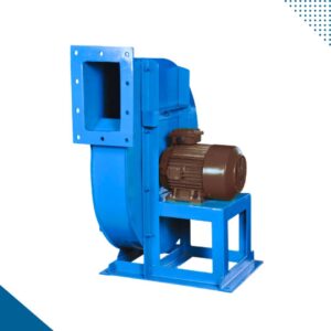
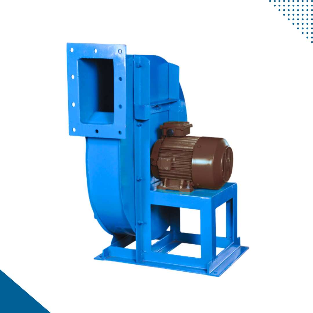
1. Centrifugal Blower :

  • Also known as radial fans or centrifugal fans
  • These blowers use a rotating impeller to create a centrifugal force that accelerates the air or gas outward from the center of the device
  • Centrifugal blowers are often used in HVAC systems, industrial ventilation, and air pollution control
  • The types include forward-curved centrifugal blowers, backward-curved centrifugal blowers, radial blowers, compact centrifugal blowers, high temperature centrifugal blowers, corrosion resistant centrifugal blowers, high pressure blowers, multistage centrifugal blower

Working Principle :

  • Impeller Rotation: The blower has an impeller with blades that rotates within a casing.
  • Air Intake: Air or gas enters the blower through an inlet.
  • Centrifugal Force: The rotating impeller imparts centrifugal force to the incoming air, causing it to move radially outward.
  • Diffusion: The outward-moving air then enters a diffuser, which slows down the air and converts kinetic energy into pressure energy.
  • Air Discharge: The air is discharged from the blower at an increased pressure and velocity.

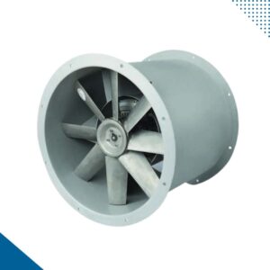
2. Axial Blower :

  • Also known as axial fans
  • Axial blowers move air parallel to the axis of the impeller
  • They are commonly used for applications such as cooling electronic equipment, providing ventilation in confined spaces, and cooling industrial processes

Working Principle :

  • Impeller Rotation: Axial blowers have an impeller that rotates around an axis parallel to the direction of the airflow.
  • Air Intake: Air enters axially, parallel to the axis of rotation.
  • Axial Flow: The impeller propels the air in a straight-through direction.
  • Air Discharge: The air exits the blower in the same axial direction.

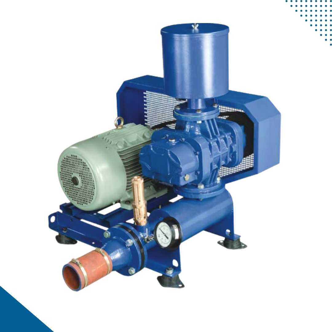
3. Positive Displacement Blowers :

  • Also known as rotary lobe blowers or rotary piston blowers.
  • These blowers utilize positive displacement to move air or gas.
  • Positive displacement blowers are often used in applications such as pneumatic conveying, wastewater treatment, and aeration in water treatment plants.

Working Principle :

  • Lobe or Screw Movement: Positive displacement blowers use rotating lobes or screws to trap and move a fixed volume of air or gas with each revolution.
  • Air Compression: As the lobes or screws rotate, they create pockets of air, compressing and displacing it through the blower.

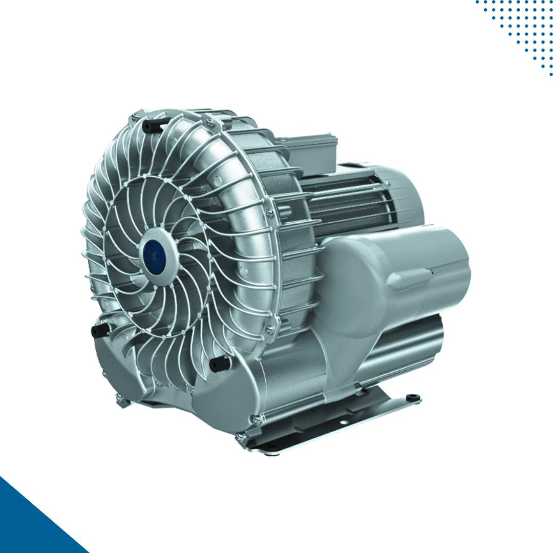
4. Regenerative Blowers :

  • Also known as side channel or ring channel blowers.
  • These blowers use the regenerative principle to create air flow.
  • They are often used in applications requiring low flow rates and moderate pressure, such as vacuum packaging, vacuum lifting and pneumatic conveying.
  • The types include single stage regenerative blowers, multistage regenerative blowers

Working Principle :

  • Impeller Spin: Regenerative blowers have an impeller with multiple blades that spin rapidly.
  • Regenerative Action: The spinning impeller generates airflow by pushing air outward to the housing walls, creating a regenerative effect.
  • Continuous Movement: The regenerative process contributes to the continuous movement of air.

5. Multistage Blowers :

  • Also known as side channel or ring channel blowers.
  • These blowers use the regenerative principle to create air flow.
  • They are often used in applications requiring low flow rates and moderate pressure, such as vacuum packaging, vacuum lifting and pneumatic conveying.
  • The types include single stage regenerative blowers, multistage regenerative blowers


Selection criteria for Blower

Selecting the right blower for a specific application involves considering various factors to ensure optimal performance and efficiency. Here are key criteria for blower selection:

Airflow Requirements:​

  • Determine the required volume of air (in cubic feet per minute or cubic meters per second) for the application.
  • Consider the variations in airflow demand and whether the blower needs to operate at a constant or variable speed.
  • Key parameters considered for calculating airflow requirements are conveying capacity, distance & number of bends in conveying line.

Pressure Requirements:​

  • Identify the system’s pressure needs, usually expressed in mm of water column (mmWC) or pascals.
  • Consider both static pressure (resistance to flow) and dynamic pressure (velocity of the air).

Temperature Considerations:

  • Evaluate the temperature of the air or gas being handled by the blower.
  • Choose a blower that can operate effectively within the specified temperature range.

Altitude & Atmospheric Conditions:

  • Account for the altitude at which the blower will operate, as this affects the air density.
  • Consider the humidity and other atmospheric conditions that might impact blower performance.

Application Type:

  • Different applications like dilute phase/dense phase pneumatic conveying, etc. require specific types of blowers (e.g., centrifugal, axial, positive displacement).
  • Consider whether the blower is needed for ventilation, material handling, pneumatic conveying, aeration, or other purposes.

Efficiency & Energy Consumption:

  • Evaluate the blower’s efficiency to ensure it meets energy efficiency standards.
  • Consider the total cost of ownership, including energy consumption and maintenance costs.
  • Choose a blower with a capacity, matching usual requirements, add a factor of safety for demand variations, and avoid overcapacity to optimize energy consumption in pneumatic conveying systems.

Operating Speed & Control:

  • Determine the required operating speed and consider if variable speed control is necessary for the application.
  • Variable speed control can optimize energy efficiency by matching the blower’s speed to the actual demand.

Noise Level:

  • Assess the noise level produced by the blower and ensure it complies with the acceptable noise standards for the application.
  • General criteria for acceptance of noise level: Noise Level < 85dB
  • Silencers, Acoustic Covers are used to reduce noise level.

Space Constraints:

  • Consider the available space for installing the blower.
  • Choose a blower that fits within the available footprint while allowing for proper ventilation and maintenance access.

Material Compatibility:

  • Verify that the blower materials are compatible with the handled air or gas, especially if it contains corrosive or abrasive elements.

Reliability & Maintenance:

  • Evaluate the blower’s reliability and ease of maintenance.
  • Choose a blower with a track record of reliability and one that is easy to access for routine maintenance tasks.

Budgetary Constraints:

  • Consider budget constraints and choose a blower that offers the best balance of performance and cost-effectiveness.

By carefully considering these criteria, engineers and system designers can select a blower that meets the specific needs of the application, ensuring efficient and reliable operation over time. For pneumatic conveying systems, the design criteria are crucial to the performance of the system, as the parameters are directly proportional to the right selection. Get in touch with subject matter experts at Indpro to know more about these selection criteria.

Different Prime Movers used in Pneumatic Conveying of Materials

Different Prime Movers used in
Pneumatic Conveying of Materials

Pneumatic conveying systems facilitate the movement of bulk materials like powder, pellets, granules grains, spices, etc. through enclosed pipelines using gas, typically air or nitrogen. Widely employed in various industries, these systems leverage gas pressure differential and flow to transport granular or powder materials. This article delves into the diverse prime movers used in pneumatic conveying systems, exploring their working principles.


What is Prime Mover?​​

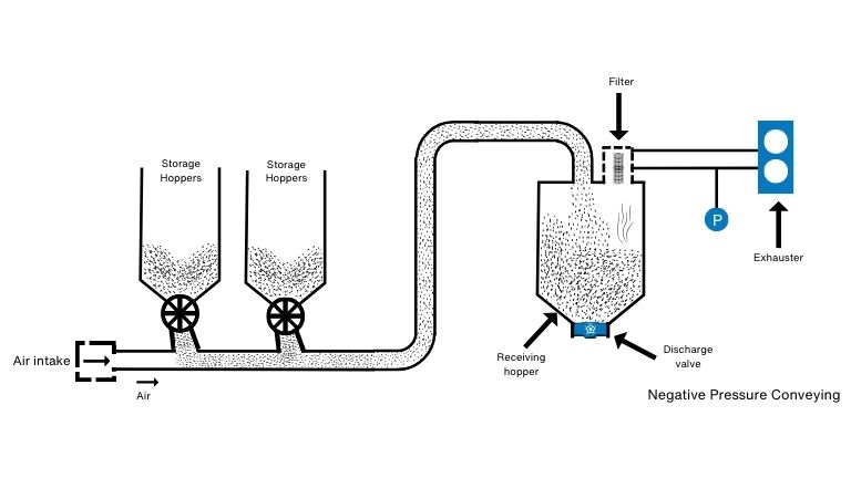
Prime mover is a vital part of pneumatic conveying system. These prime movers serve as the driving force to propel gas within the pipelines in pneumatic conveying systems. The key types include compressors, blowers, and vacuum pumps.

Types of Prime Mover -


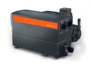
1. Vacuum pump: Function, Working principle & Types​

Function of Vacuum Pump – A vacuum pump is a device designed to eliminate gas molecules or air particles from a sealed volume, creating a pressure difference and generating a partial vacuum.

Working Principle & Types of Vacuum Pumps

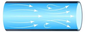
The fundamental principles of vacuum pumping can be broadly classified into two main categories: gas transfer and entrapment. Gas transfer itself can be subdivided into two distinct methods known as positive displacement and momentum transfer. Understanding the three types of flow: viscous, transitional, and molecular—provides a deeper insight into the concepts of vacuum pumps.

Viscous/continuous flow:

Viscous flow takes place at high pressures to medium vacuum levels. In this scenario, the gas is dense enough for gas molecules to collide with each other. The mean free path, which represents the average distance a gas molecule travels, is shorter than the dimensions of the chamber. As the vacuum level increases, gas molecules are more likely to collide with the chamber walls than with other gas molecules.

Transitional flow:

Transitional flow occurs when viscous flow begins to transition into molecular flow. This shift happens as the mean free path of gas molecules becomes comparable to or exceeds the dimensions of the chamber.

Molecular flow:

Molecular flow is defined by the random motion of gases, where the mean free path of gas molecules is notably greater than the dimensions of the chamber. In this scenario, collisions between gas molecules are infrequent, and their movement is primarily determined by the chamber’s geometry. Positive displacement pumps can mechanically pump fluids that are flowing under viscous conditions. However, when the gas cannot be evacuated by pressure difference, molecular flow is reached When fluids transition into molecular flow, positive displacement pumps become inadequate. In such situations, additional pumping systems like momentum transfer or entrapment pumps are employed to maintain the required vacuum levels.  In most high vacuum systems, two pumps are typically employed together. Positive displacement pumps alone prove insufficient for achieving higher vacuum levels. Momentum transfer pumps run the risk of stalling when the system operates under viscous flow conditions. Entrapment pumps may require frequent regeneration or emptying, particularly when dealing with high gas volumes, especially in situations involving viscous flow.

i. Positive Displacement Vacuum Pumps:

Positive displacement vacuum pumps function by alternately expanding and contracting a sealed chamber, with the flow of fluid regulated by one-way valves. The process begins with the expansion of a sealed chamber, creating a vacuum that draws fluid through an intake valve. As the chamber reaches maximum expansion, the intake valve closes, and the exhaust valve opens. As the chamber compresses or contracts, the fluid is expelled. This cycle repeats multiple times per second, generating a pulsating flow. There are two main types of positive displacement pumps – Reciprocating (Piston Pump, Plunger Pump, Diaphragm Pump) & Rotary (Vane Pump, Liquid Ring Pump, Rotary Piston Pump, Screw Pump, Gear Pump, Lobe Pump)

ii. Momentum Transfer Vacuum Pumps:

Momentum transfer pumps operate by inducing the movement of gas or liquid molecules through the transfer of kinetic energy. This occurs at the molecular flow level, in contrast to the viscous or continuous flow observed in positive displacement pumps. Its types include Turbomolecular Pump & Diffusion Pump.

iii. Entrapment Vacuum Pumps:

Entrapment vacuum pumps utilize various physical and chemical phenomena to capture gas molecules. These pumps operate in high vacuum regimes without causing oil contamination. Its types include Cryogenic pump, Sorption Pump, Sputter Ion Pump, Centrifugal Pumps.


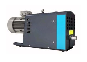
2. Blower: Function, Working principle & Types

  • Function of Blower : Function of blower is to move air and gas at low to high pressure to perform a specific function. Blowers play a versatile role in numerous industries, serving various applications such as cooling, conveying, ventilating, exhausting, and more.
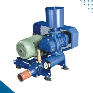
  • Working Principle of Blower: An air blower utilizes a rotating impeller or rotor to generate a vacuum, drawing air into the blower. As the air enters the center of the impeller, it is separated by the rotating blades. The centrifugal force increases both the speed and volume of the air stream within the housing

Types of Blowers -

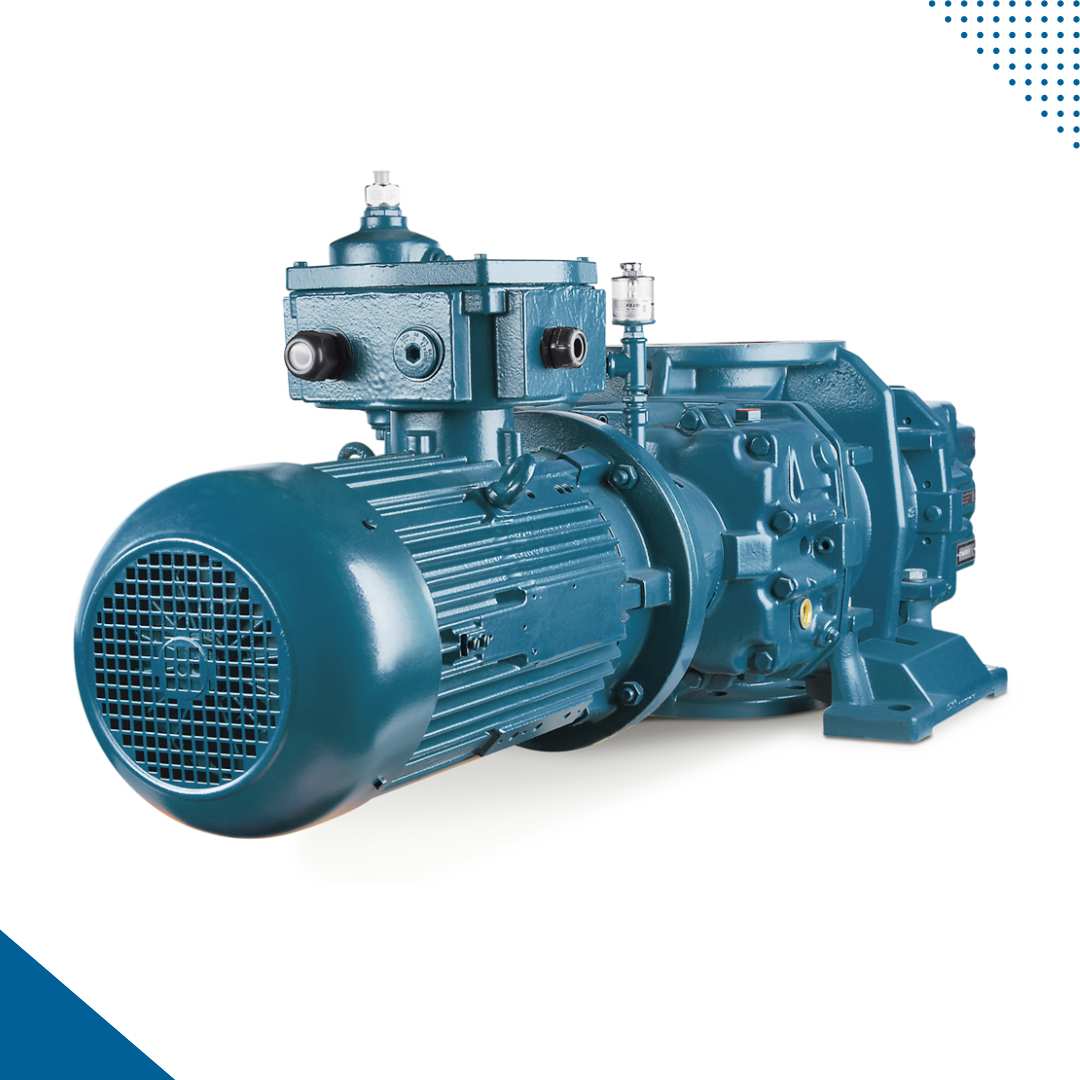
i. Positive Displacement Blowers:

A positive displacement blower operates to maintain a consistent flow and speed regardless of changes in pressure. This characteristic makes it well-suited for moving neutral and air gases. The blower effectively removes gas through the decreasing section, trapping and releasing air in a cyclical manner. There are two distinct types available – the Rotary Lobe Blower and the Helical Screw Blower.

ii. Centrifugal Blowers:

A centrifugal blower is effective in controlling air pollution and facilitating gas transportation. This type of blower is commonly employed for ventilation purposes, operating by altering the direction of airflow with a 90-degree turn. Continuous gas transfer is achieved as the gas passes through the centrifugal blower, increasing kinetic energy. Equipped with rotating impellers, these blowers are suitable for applications requiring variable flow with high pressure.

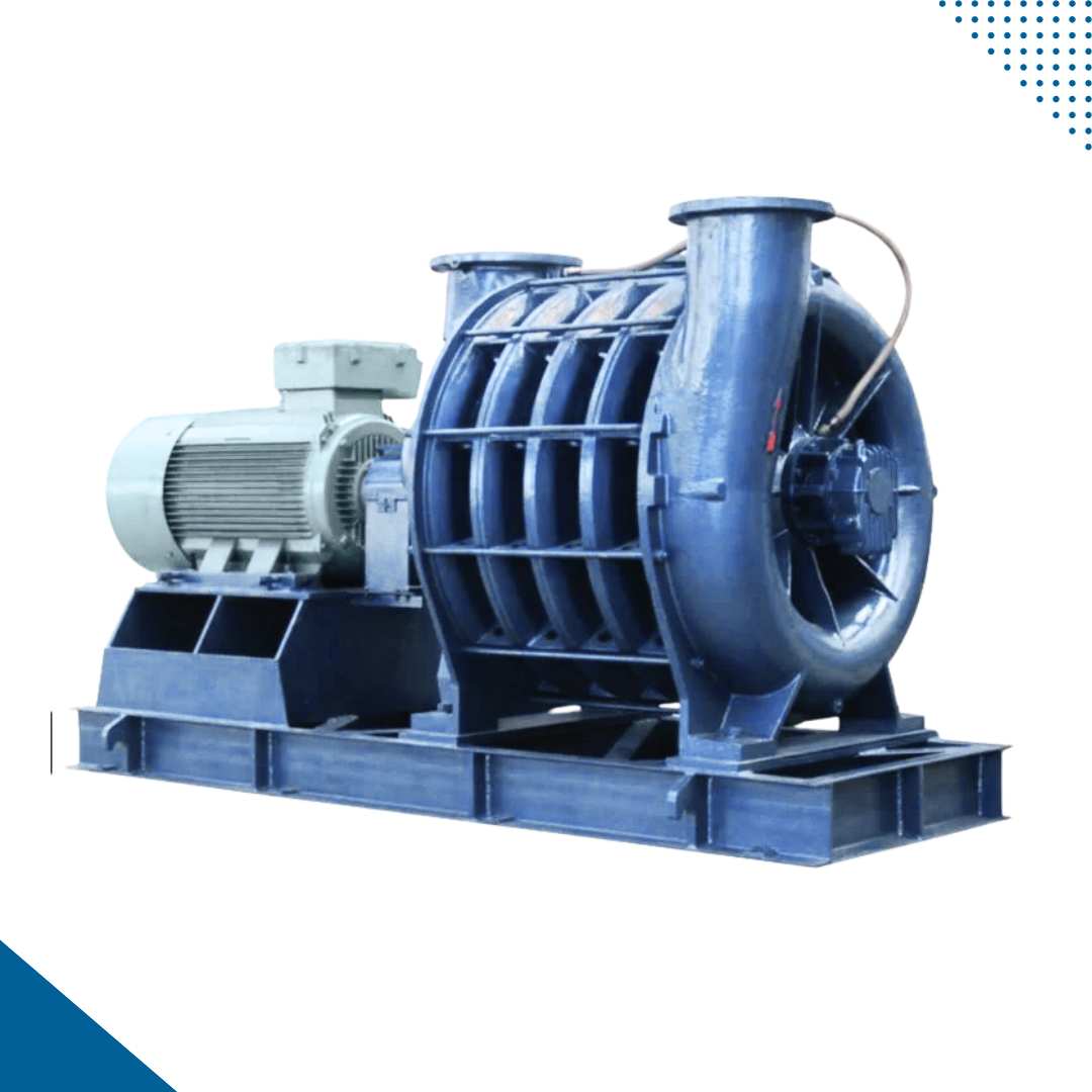
iii. Multistage Centrifugal Blowers:

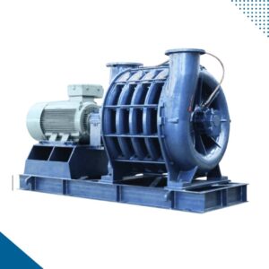
Multistage centrifugal blowers are a specific type within the centrifugal blower category. These blowers utilize multiple stages to rotate the machine and increase air pressure. Equipped with an electric motor that provides high-pressure tolerance, they are suitable for applications with high flow rates. Multistage centrifugal blowers find utility in various sectors, such as the wastewater treatment industry, powering artificial lungs, and boosting landfill gas.

iv. High-Speed Blowers:

High-speed blowers are designed to provide both high pressure and high flow, making them versatile for various applications. These blowers typically feature impellers on each side, directly coupled to a motor. The ability to connect them to a permanent magnet motor with a variable frequency drive allows for efficient control and adjustment based on specific operational needs.

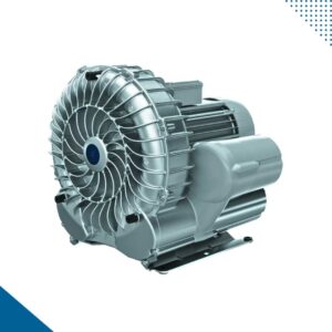
v. Regenerative Blowers:

A regenerative blower is characterized by oil-free components, making maintenance relatively easy. Ideal for applications requiring low pressure, these blowers operate by displacing air molecules and creating pressure through non-positive displacement, forcing the air to move.


3. Compressor: Function, Working principle & Types

  • Function of Compressor: A compressor is a device designed to compress air or other gases, elevating their pressure beyond atmospheric levels. It takes in air from the atmosphere and increases its pressure through compression.

  • Working principle & types of compressors: To explain the working principle of air compressors, it’s crucial to differentiate between various types of compressors: reciprocating (piston) and rotary (screw) compressors.

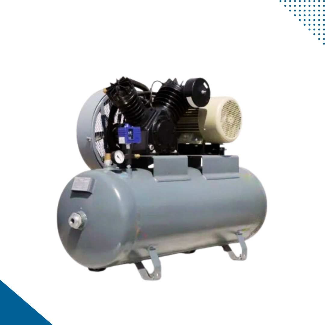
i. Reciprocating Compressor:

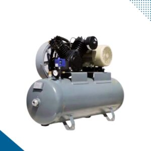
In a reciprocating compressor, air compression occurs through cylinders, pistons, and cranks. These components, driven by an electric or combustion engine, draw air into the cylinder and compress it using pistons. The compression process may consist of one or multiple stages until the desired operational pressure is reached. The compressed air then passes through a cooler into the air tank. These are used by many industries which includes Chemical, Petrochemical, Oil & Gas, Refrigeration, etc. Reciprocating compressors come in various types, including Single Acting, Double Acting, Single Stage, and Double Stage.

ii. Rotary Compressor:

Rotary compressors operate differently from reciprocating compressors. Instead of using pistons and cylinders for compression, rotary compressors employ rotating screws to initiate compression. Air is forced between two rotating screw elements, resulting in compressed air. As the compression generates heat, a cooling liquid, often oil, is injected into the compression chamber. This cooling liquid circulates between the cooling chamber, liquid tanks, and coolers to maintain the operating temperature around 80°CThese are utilized in various industries, including the food sector. Packaging sector, Automotive sector, etc. The types rotary compressors include Rotary Screw compressor which is most widely used, Scroll Type compressors, Vane Type compressors & Lobe Type compressors.


Selecting the Right Prime Mover for Pneumatic Conveying System

Choosing the appropriate prime mover for your specific system is of greatest importance in optimizing operational efficiency and lifespan of equipment. Below are some guidelines for selection of right prime mover for pneumatic conveying system:

Fan

It is used when working with dilute phase pneumatic conveying systems (both pressure as well as vacuum based) with low solids-to-air ratio

Lobe Blower

It is used when working with dilute phase pneumatic conveying system (both pressure as well as vacuum based) with high solids to air ratio

Vacuum Pump

It is used when working with dense phase vacuum type pneumatic conveying system

Compressor

It is used when working with dense phase pressure type pneumatic conveying system

Battery Recycling Process of Lead-Acid and Lithium-Ion

Battery Recycling Process

In contemporary times, numerous types of equipment operate on either batteries or gas. The shared characteristic between these two elements is their finite usage; once depleted, the customary practice involves refilling gas or disposing of used batteries and acquiring replacements.

Nevertheless, discarding batteries can contribute significantly to environmental waste, given their widespread use and the presence of harmful materials within them. Consequently, disposing of batteries may not be a prudent course of action. An alternative to discarding used batteries is recycling them.

In contrast to materials like plastic and paper, battery recycling may not be as widely understood. Therefore, we’ve compiled this article to provide you with a fundamental understanding of battery recycling.

Battery Recycling Process Banner

What is battery recycling?

Battery recycling is a vital practice that involves the reuse and reprocessing of batteries, with the primary objective of reducing the volume of batteries being discarded as material waste. Batteries contain a range of hazardous chemicals and heavy metals, and their improper disposal has raised significant environmental concerns, including the contamination of water and soil. Therefore, battery recycling is essential to align with environmental and health regulations, as well as to reap associated benefits.

Batteries, by their nature, have a finite lifespan. Eventually, they either become damaged or cease to function. This is precisely when battery recycling becomes crucial.

How the batteries are recycled?

It is important to understand the process of recycling batteries. There are various types of technologies and material used to produce batteries which must be considered before delving into the recycling process.
Batteries exhibit variations based on their constituent components, which encompass lead-acid, lithium-ion (Li-ion), nickel-metal hydride (Ni-MH), nickel-cadmium (Ni-Cd), lithium-ion polymer, nickel-zinc, and alkaline materials. Manufacturers utilize these components to create various types of batteries, each potentially differing in terms of their intended applications, power output, and the specific recycling processes they entail.


Recycling process of Lead-Acid Batteries​

Lead-acid batteries hold the distinction of being the earliest form of rechargeable batteries worldwide. They are composed of a combination of lead and sulfuric acid.

Recycling process of Lead-Acid Batteries

1. Collection:

The initial step in the battery recycling process entails the collection of discarded lead batteries from various disposal points.

2. Crushing :

Following the collection phase, the subsequent step in the recycling of lead batteries involves their disassembly. Recycling facilities employ mills or industrial crushers to crush the batteries into smaller fragments during this phase.

After crushing, the material is stored in small bags, jumbo bags, or in some permanent storage unit and then it is transferred to the sorting station. Automation solutions can include bag filling machine, big bag unloading station, bag dump station, and pneumatic conveying system for the crushed material to be conveyed to multiple storage silos for storing, and then as per the requirement, it can extract from those silos.

3. Sorting:

In this phase, the lead-acid battery components are meticulously separated. Recyclers distinguish and segregate the plastic and paper components from the lead and metal parts of the battery. The lead and heavy metals extracted from the battery then undergo subsequent processing for recycling.

4. Sieving:

Within this process, recyclers carry out the removal of thermoplastic components present in the battery. Following this, they utilize a sieving process to extract the liquid contents from the battery, leaving behind the dry lead components. Subsequently, the lead and heavy metals proceed to the final stage of the recycling process.
After the sieving operation, dry lead which is in powder form is passed through a cyclone separator to discharge the powder material into the collection unit which is further connected to the extraction process. Automation systems include a cyclone separator & dust collection system which will smoothly carry out the operation for feeding material into the collection unit and the generated dust shall be transferred to the centralized dust collection unit.

The scrap plastic materials from batteries are collected in the warehouse in a loose form and then they get transferred to the washing lines using a pneumatic conveying system for the extraction process. These reprocessed thermoplastics are used to create battery casings and other new plastic products by manufacturers.

5. Extraction:

In the last phase of lead-acid battery recycling, recyclers extract the lead powder and heavy metal components from the remaining battery remnants.

This procedure can be executed in two distinct manners:

Pyrometallurgy based – Pyrometallurgy is a metallurgical process that relies on heat for the extraction and purification of metals. It involves roasting, smelting and refining.

Hydrometallurgy based – Hydrometallurgy is the method employed for extracting metals from ore. It involves leaching, solution-based concentration, and purification & metal recovery.

Both hydrometallurgy and pyrometallurgy ultimately yield molten lead as the end product. Recyclers then shape this molten lead and deliver it to manufacturers to be used in the production of new batteries.


Recycling process of Alkaline Zinc Air /Zinc Carbon Batteries

Recycling alkaline batteries involves a mechanical dismantling process. Similar to other types of batteries, the initial step is the collection of used alkaline batteries. Subsequently, the batteries are sorted after being dismantled.
Following the disassembly of alkaline batteries, recyclers extract three key components for additional processing: steel components, plastic and paper components, and zinc and manganese components.

Subsequently, these materials are packed & sent to recycling facilities, where manufacturers recover them for the production of new products.


Recycling process of Lithium Ion, Nickel Metal Hydride, Nickel-Cadmium Batteries

Lithium-ion (Li-ion) batteries, commonly employed in cars and electronic devices, are rechargeable. Nickel-based batteries, another rechargeable type, find use in portable devices such as cameras and in home or office UPS devices.

Both lithium-ion (Li-ion) and nickel-based batteries share similarities with lead-acid batteries in the final stages of recycling. Here is a detailed step-by-step process for recycling lithium and nickel batteries.

Recycling process of Lithium Ion

Step 1: Collection

Recyclers collect used lithium and nickel batteries from collection points or various other locations.

Step 2: Sorting

During this phase, recyclers carefully separate the plastic materials within the battery from the metal components. Both of these materials can be effectively repurposed in the creation of new products.

Step 3: Shredding

The sorted batteries are passed through a shredder which breaks the battery into coarse particles. After shredding, the coarse material is then transferred to the crushing station using a conveying system.

Step 5: Smelting

In this phase, the components of lithium-ion and nickel-based batteries undergo a process known as High-Temperature Metal Reclamation. During this process, metals present in the batteries, such as nickel, manganese, chromium, and iron, are extracted, conveyed via line to packaging station & and sent to manufacture new products.

Step 4: Crushing

The different types of shredded materials are then crushed into fine particles by using a mill or crusher, and collected material gets conveyed using a conveying system to the smelting process.

Recycling process of Mercury Batteries​

Mercury batteries, after collection, undergo recycling through liquid and heat extraction methods. These batteries contain highly toxic heavy metals, necessitating their processing in carefully controlled extraction environments to minimize environmental and health risks.
The mercury obtained through these extraction processes serves as a valuable resource for manufacturing new mercury batteries, measuring instruments, and components for fluorescent lights. Additionally, manufacturers can repurpose the plastic and other materials obtained from the batteries to create various new products.

Benefits of battery recycling

  • Conservation of Non-Renewable Resources
  • Prevents pollution
  • Minimizes solid waste deposited in landfills
  • Energy saving