Indpro Logo

Indpro
Typically replies within an hour

Indpro
"Hello!👋

How can I help you today with your bulk material handling needs?"
×
Chat with Us

How to Convey PVC Powder Without Segregation

How to Convey PVC Powder Without Segregation

In PVC processing plants, maintaining a homogeneous powder mixture during material transfer is just as important as maintaining throughput. A perfectly formulated PVC dry blend can lose its designed characteristics if segregation occurs during conveying. This often results in inconsistent extrusion performance, unstable product quality, increased rejects, and unnecessary process adjustments.

Many engineers consider pneumatic conveying to be merely a means of transporting material from Point A to Point B. In reality, it is a process operation that directly influences the physical characteristics of the material. Every bend, velocity change, air distribution, cyclone, diverter valve, hopper, and discharge point has the potential to alter the composition of the blend.


The challenge becomes even greater because PVC dry blends are not single-component materials. They consist of PVC resin combined with stabilizers, lubricants, fillers, pigments, processing aids, impact modifiers, and various additives – each having different particle sizes, densities, and flow characteristics.

Designing a conveying system that preserves this carefully engineered mixture requires a deep understanding of powder behavior, particle dynamics, and conveying physics.

This article explores the engineering principles behind segregation, identifies where it occurs, and explains how properly designed pneumatic conveying systems can transport PVC powder while maintaining blend uniformity.


Understanding PVC Powder

Unlike free-flowing polymer pellets, PVC is often conveyed as a fine cohesive powder.

A typical PVC dry blend consists of:

ComponentTypical Characteristics
PVC ResinFine powder
Calcium CarbonateHigher bulk density
Titanium DioxideExtremely fine and cohesive particles
Heat StabilizersFine additives
LubricantsLight, waxy particles
Processing AidsFine polymer powders
PigmentsUltra-fine particles
Impact ModifiersLow-density powder

Although these ingredients appear uniformly mixed after blending, they possess significantly different:

  • Particle size distributions
  • Bulk densities
  • Particle shapes
  • Aeration characteristics
  • Surface friction
  • Cohesiveness
  • Fluidization behavior
The conveying system must therefore preserve – not segregate – the homogeneity established in the high-speed mixer.


Why Segregation Occurs

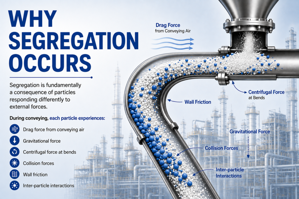
Segregation is fundamentally a consequence of particles responding differently to external forces.

During conveying, each particle experiences:

  • Drag force from conveying air
  • Gravitational force
  • Centrifugal force at bends
  • Collision forces
  • Wall friction
  • Inter-particle interactions 
Since every ingredient has different physical properties, they do not respond identically.
 
Over long conveying distances, these differences accumulate until the original blend gradually separates.
 
The result is a mixture arriving at the destination with a composition different from what left the blender.

why segregation occurs


The Physics Behind Powder Segregation

Segregation is rarely caused by one mechanism alone. It is typically a combination of several physical phenomena acting simultaneously.

1. Particle Size Segregation

Fine particles experience greater aerodynamic drag than coarse particles.

Coarser particles possess greater inertia and tend to remain concentrated near the centre of the conveying stream, while ultrafine particles follow turbulent airflow patterns more readily.

Repeated acceleration and deceleration gradually create local concentration differences.

Higher velocities increase pellet kinetic energy dramatically.
Since kinetic energy varies with velocity squared,  KE=1/2 mv^2
 

A 20% increase in air velocity increases impact energy by 44%!

2. Density Segregation

Calcium carbonate has considerably higher density than PVC resin.

During velocity fluctuations:

  • Heavier particles resist acceleration
  • Lighter particles accelerate rapidly.
These different responses cause spatial separation within the conveying pipeline.
 
3. Air Classification 
 
Whenever air velocity decreases suddenly – such as in receivers, cyclones, or silos – particles settle at different rates.
 
Large dense particles fall quickly.
 
Fine additives remain suspended longer.
 
Without proper design, air classification changes the local composition of the blend.
 
4. Fluidization Effects
 
PVC dry blends often become partially fluidized.
 
Low-density particles remain suspended while heavier particles settle.
 
Poorly designed hoppers amplify this phenomenon, causing selective discharge.
 
5. Percolation
During vibration or movement: 
 
  • Small particles migrate downward through voids.
  • Larger particles rise upward.
This “Brazil Nut Effect” is well known in powder technology and can occur in improperly designed storage vessels.


Segregation During Pneumatic Conveying

Although many engineers focus on pipelines, segregation can occur at every stage.

1. Feeding

  • Incorrect rotary valve selection
  • Uneven screw feeder discharge
  • Air leakage
  • Non-uniform feed rates
  • All disturb the blend before conveying even begins 

2. Pipeline Entry

High acceleration zones create differential particle velocities. Some additives immediately migrate toward the pipe wall.

3. Straight Pipelines

Turbulence continually redistributes particles. Over long distances this redistribution can become non-uniform.

4. Pipe Bends

Bends are the most critical locations. Heavier particles possess greater momentum. They impact the outer wall while lighter particles remain closer to the air stream. Repeated bends gradually separate the mixture.

5. Cyclones and Receivers

Poor cyclone efficiency may preferentially carry fine additives into dust collectors. The product entering the silo may therefore differ slightly from the original blend.

6. Storage Silos

Even if conveying is perfect, poor silo design can reintroduce segregation through funnel flow, rat-holing, or stagnant zones.


Engineering Laws Governing PVC Powder Segregation

The movement of every particle in a pneumatic conveying system is governed by classical mechanics, fluid dynamics, and bulk solids science. Understanding these principles enables engineers to design systems that maintain blend uniformity rather than inadvertently promoting segregation.

Engineering Law / PrincipleGoverning EquationImpact on PVC Powder ConveyingEngineering Design Consideration
Newton’s Second LawF = maParticles of different masses accelerate differently under the same airflow, leading to velocity differences and segregation.Minimize sudden acceleration and deceleration zones; ensure uniform material feeding.
Stokes’ LawFd = 3πμdVFine particles experience higher drag relative to their mass and remain suspended longer than coarse particles.Prevent air classification by maintaining stable conveying conditions and properly designed receivers.
Terminal Settling VelocityDepends on particle size, density and dragParticles settle whenever conveying velocity falls below their terminal settling velocity.Maintain conveying velocity above settling velocity but below excessive turbulence limits.
Reynolds NumberRe = ρVD / μDetermines airflow regime. High turbulence increases random particle motion and segregation.Optimize airflow to achieve stable suspension without excessive turbulence.
Bernoulli’s PrinciplePressure decreases as velocity increasesPressure changes at bends, tees and transitions alter local airflow, causing uneven particle movement.Avoid abrupt expansions and contractions; maintain smooth pipeline transitions.
Momentum Conservationp = mvDense particles possess greater momentum and tend to continue straight at bends while lighter particles follow airflow.Select long-radius bends and optimized pipeline layouts.
Centrifugal ForceFc = mv²/rHigher conveying velocities dramatically increase centrifugal separation at bends.Use low conveying velocities and large-radius bends wherever possible.
Minimum Fluidization VelocityMaterial specificLight particles remain fluidized while heavy particles settle, causing segregation in receivers and silos.Design hoppers and receivers to avoid uncontrolled fluidization.
Janssen’s TheoryBulk solids pressure theoryWall friction causes uneven stress distribution leading to stagnant zones and funnel flow.Design silos to eliminate dead zones and ensure complete material movement.
Jenike’s Mass Flow TheoryHopper flow theoryFunnel-flow hoppers promote segregation during discharge.Design mass-flow hoppers using measured flow properties rather than empirical angles.
Kinetic Energy PrincipleKE = ½mv²Particle impact energy increases with the square of conveying velocity, increasing separation and attrition.Operate at the lowest stable conveying velocity rather than the highest possible velocity.


Engineering Strategies to Eliminate Segregation

The objective of pneumatic conveying is not simply to move powder – it is to preserve its engineered composition.

The following design practices significantly reduce segregation:

Engineering StrategyTechnical Rationale
Maintain optimum conveying velocityPrevents excessive turbulence while avoiding particle settling.
Ensure uniform solids loadingReduces particle independence and maintains collective movement.
Design smooth pipeline layoutsMinimizes pressure fluctuations and particle separation.
Use engineered long-radius bendsReduces centrifugal forces and wall impacts.
Control air distributionPrevents localized acceleration and air classification.
Select appropriate pipeline diameterBalances conveying velocity and solids loading ratio.
Design efficient receiversPrevents selective removal of fine additives.
Implement mass-flow storageMaintains first-in-first-out discharge and blend consistency.
Characterize powder propertiesEnables design based on measured flow behavior rather than assumptions.


The Engineering Philosophy

One of the most important lessons in pneumatic conveying is that segregation is fundamentally an energy-driven phenomenon.

Since centrifugal force and kinetic energy both increase with the square of conveying velocity, even a modest increase in air velocity can dramatically amplify particle separation, wall impacts, and material degradation.

Therefore, the guiding principle for PVC powder conveying should be:

Transport the material at the lowest stable conveying velocity that ensures reliable movement while preserving blend homogeneity.”
 

This philosophy shifts the focus from maximizing conveying speed to optimizing conveying conditions—an approach that delivers superior product quality, reduced maintenance, lower energy consumption, and improved process reliability.


Conclusion:


Preventing segregation during PVC powder conveying is not achieved through a single piece of equipment or by selecting dense phase over dilute phase. It is the outcome of a carefully engineered system in which every component – from feeding and conveying to separation and storage – is designed to preserve the blend created in the mixer.

A successful PVC conveying system should do more than transport material efficiently. It should ensure that every kilogram reaching the extrusion line is compositionally identical to the material that left the blender. Achieving this requires an understanding of particle mechanics, powder flow, airflow dynamics, and equipment interaction.

As PVC processors pursue higher product consistency, reduced waste, and greater automation, conveying systems will increasingly be evaluated not only by their capacity but also by their ability to protect material integrity. In modern powder handling, preserving blend uniformity is no longer an operational preference – it is a defining measure of engineering excellence.

How to Eliminate Angel Hair in Polymer Conveying: An Engineering Guide

How to Eliminate Angel Hair in Polymer Conveying:
An Engineering Guide

For polymer processors, compounders, masterbatch manufacturers, resin producers, and packaging manufacturers, product quality begins long before extrusion or molding. The integrity of every polymer pellet transported through the plant directly influences production efficiency, product consistency, equipment reliability, and ultimately customer satisfaction.

One of the most persistent yet underestimated problems in polymer conveying systems is angel hair formation – the generation of extremely thin polymer filaments that originate during high-velocity pellet transport. While these fine strands may appear insignificant initially, they progressively evolve into streamers, dust, and fused agglomerates that contaminate production lines, clog filters, interfere with feeding systems, and reduce overall plant efficiency.

Unlike conventional maintenance issues, angel hair is fundamentally an engineering problem involving conveying velocity, material science, pipeline geometry, air dynamics, electrostatic effects, and equipment design.

The encouraging aspect is that angel hair is largely preventable. With correctly engineered conveying systems, its generation can be minimized to near-zero levels.

This article explores the science behind angel hair formation, explains why it occurs, and presents engineering solutions for designing polymer conveying systems that eliminate the problem at its source.


Understanding Angel Hair Formation

What is Angel Hair?

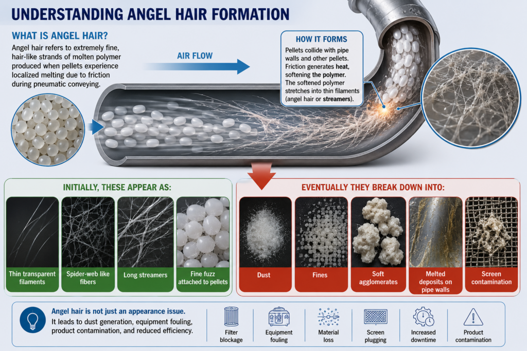
Angel hair refers to extremely fine, hair-like strands of molten polymer produced when pellets experience localized melting due to friction during pneumatic conveying.

Initially, these appear as:

  • Thin transparent filaments 
  • Spider-web like fibers 
  • Long streamers 
  • Fine fuzz attached to pellets 

Eventually they break down into:

  • Dust 
  • Fines 
  • Soft agglomerates 
  • Melted deposits on pipe walls 
  • Screen contamination 
What is Angle Hair

Unlike degraded polymer resulting from thermal processing, angel hair is generated solely during mechanical conveying. 


The Physics Behind Angel Hair Formation

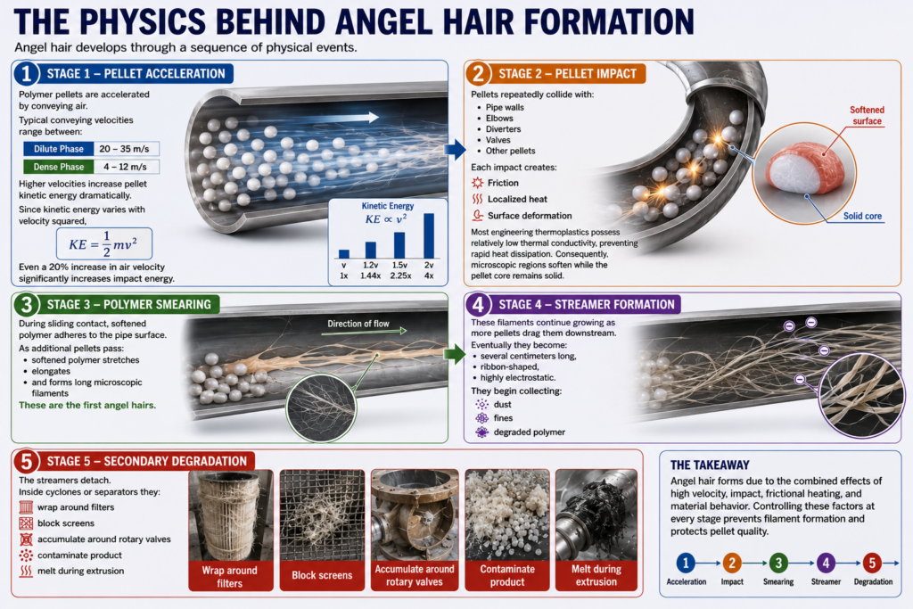
Angel hair develops through a sequence of physical events.

Stage 1 – Pellet Acceleration

Polymer pellets are accelerated by conveying air. Typical conveying velocities range between:

  • Dilute Phase: 20 – 35 m/s 
  • Dense Phase: 4 – 12 m/s 
Higher velocities increase pellet kinetic energy dramatically.
Since kinetic energy varies with velocity squared,  KE=1/2 mv^2
 

A 20% increase in air velocity increases impact energy by 44%!

Stage 2 – Pellet Impact

Pellets repeatedly collide with:

  • Pipe walls 
  • Elbows 
  • Diverters 
  • Valves 
  • Other pellets 
Each impact creates:
 
  • Friction 
  • Localized heat 
  • Surface deformation 
Most engineering thermoplastics possess relatively low thermal conductivity, preventing rapid heat dissipation.
 
Consequently, microscopic regions soften while the pellet core remains solid.
 

Stage 3 – Polymer Smearing

During sliding contact, softened polymer adheres to the pipe surface.

As additional pellets pass:

  • softened polymer stretches 
  • elongates
  • and forms long microscopic filaments
These are the first angel hairs.
 

Angel hair develops through a sequence of physical events.

Stage 1 – Pellet Acceleration

Polymer pellets are accelerated by conveying air. Typical conveying velocities range between:

  • Dilute Phase: 20 – 35 m/s 
  • Dense Phase: 4 – 12 m/s 
Higher velocities increase pellet kinetic energy dramatically.
Since kinetic energy varies with velocity squared,  


A 20% increase in air velocity increases impact energy by 44%!


Stage 2 – Pellet Impact

Pellets repeatedly collide with:

  • Pipe walls 
  • Elbows 
  • Diverters 
  • Valves 
  • Other pellets 
Each impact creates:
 
  • Friction 
  • Localized heat 
  • Surface deformation 
Most engineering thermoplastics possess relatively low thermal conductivity, preventing rapid heat dissipation.
 
Consequently, microscopic regions soften while the pellet core remains solid. 

Stage 3 – Polymer Smearing

During sliding contact, softened polymer adheres to the pipe surface.

As additional pellets pass:

  • softened polymer stretches 
  • elongates
  • and forms long microscopic filaments
These are the first angel hairs.

Stage 4 – Streamer Formation

These filaments continue growing as more pellets drag them downstream.

Eventually they become:

  • several centimeters long, 
  • ribbon-shaped, 
  • highly electrostatic.  
They begin collecting: 
 
  • dust, 
  • fines, 
  • degraded polymer.  

Stage 5– Secondary Degradation 

The streamers detach.As additional pellets pass:

Inside cyclones or separators, they:

  • wrap around filters 
  • block screens 
  • accumulate around rotary valves 
  • contaminate product 
  • melt during extrusion

Angel Hair Formation Physics


Engineering Principles Behind Angel Hair Formation

Angel hair formation is not merely a consequence of “high conveying velocity”; it is the result of multiple engineering phenomena occurring simultaneously. Understanding these underlying principles enables engineers to design conveying systems that prevent degradation at its source rather than relying on downstream corrective measures.

1. Tribology: The Science of Friction and Wear

At its core, angel hair formation is a tribological phenomenon. Tribology is the science of friction, wear, and lubrication between interacting surfaces in relative motion.

During pneumatic conveying, polymer pellets repeatedly interact with:

  • Pipeline walls 
  • Pipe bends and elbows 
  • Diverter valves 
  • Other moving pellets 

Each interaction generates frictional forces that convert mechanical energy into heat. Although the bulk conveying air temperature may remain close to ambient, localized contact regions experience significantly higher temperatures due to friction.

The amount of frictional energy generated is governed by Coulomb’s Law of Friction: F=μN

Where:

F = Frictional force 

μ = Coefficient of friction 

N = Normal contact force

Reducing either the coefficient of friction or the impact force through optimized conveying velocities, smoother pipe surfaces, and improved pipeline layouts directly minimizes the likelihood of polymer softening. 

2. Blok’s Flash Temperature Theory

One of the most important yet often overlooked mechanisms responsible for angel hair is Flash Temperature Theory, first proposed by Dutch engineer Hugo Blok.

Unlike bulk temperature measurements, flash temperature refers to the instantaneous microscopic temperature rise occurring at the exact point where two surfaces slide against each other.

During pellet-wall contact:

  • Contact duration is only a few milliseconds. 
  • The contact area is extremely small. 
  • Frictional energy is concentrated within microscopic regions. 

As a result, localized temperatures can briefly exceed the polymer’s softening or Vicat temperature even though the average conveying temperature remains far below the melting point.

These softened regions are then stretched by subsequent pellets into the thin filaments known as angel hair.

3. Hertzian Contact Mechanics

Every collision between a polymer pellet and a conveying pipeline creates localized stresses described by Hertzian Contact Theory.

Although pneumatic conveying systems operate at relatively low pressures, the actual contact area between a spherical pellet and the pipeline wall is extremely small. Consequently, the localized contact stress can become remarkably high.During pellet-wall contact:

Repeated impacts lead to:

  • Surface deformation 
  • Increased friction 
  • Micro-scale heat generation 
  • Polymer softening 
  • Initiation of streamer formation  

This explains why improperly designed elbows and sudden directional changes are often the primary locations where angel hair begins to develop.

4. Viscoelastic Behaviour of Thermoplastics

Unlike brittle materials, thermoplastics exhibit viscoelastic behaviour, possessing both elastic and viscous characteristics.

When exposed to localized frictional heating:

  • The pellet surface softens. 
  • The polymer becomes ductile rather than brittle. 
  • Instead of fracturing, the softened polymer elongates under tensile forces.  

This unique viscoelastic response enables polymer surfaces to stretch into extremely thin continuous filaments, which subsequently develop into streamers and eventually break down into fines and dust.

Materials such as LDPE, LLDPE, and HDPE are particularly susceptible because of their relatively low softening temperatures and high elongation characteristics.

5. Fluid Dynamics and Conveying Velocity

The airflow characteristics within pneumatic conveying systems are governed by fundamental principles of fluid dynamics.

Pressure losses through conveying pipelines can be approximated using the Darcy-Weisbach Equation: 

where: 

ΔP = Pressure drop 

f = Friction factor 

L = Pipeline length 

D = Pipe diameter 

ρ = Air density 

V = Air velocity


The equation demonstrates that pressure loss increases approximately with the square of conveying velocity. Consequently, increasing blower speed not only raises energy consumption but also significantly increases pellet impact energy, frictional heating, and the likelihood of angel hair formation.


Engineering Design Strategies to Eliminate Angel Hair

An effective solution requires addressing the root causes rather than treating the symptoms. Best practices include:

1. Design for the Lowest Practical Conveying Velocity

Balance pickup velocity with stable transport, avoiding unnecessary safety margins that increase pellet impact energy.

2. Optimize Pipeline Routing

Use the shortest practical route with minimal directional changes, long-radius bends, and smooth transitions.

3. Specify Wear-Resistant, Low-Friction Components

Employ polished stainless-steel pipelines, specialized elbows, and abrasion-resistant linings where appropriate.

4. Optimize Air-to-Material Ratio

Use engineering calculations rather than rules of thumb to maintain stable conveying conditions across the full operating range.

5. Implement Variable-Speed Air Control

Variable frequency drives (VFDs) on blowers enable conveying velocity to be matched to throughput, preventing over-conveying during partial loads.

6. Install Efficient Separation Systems

Cyclones, receiver bins, and filtration systems should minimize pellet impact while effectively removing conveying air.

7. Monitor System Performance

Track differential pressure, airflow, pellet breakage, dust levels, and pipeline wear to detect conditions that promote angel hair before they become chronic.


Beyond Prevention: Technologies for Removing Residual Angel Hair

While optimized conveying system design remains the most effective method for eliminating angel hair, some applications – particularly high-throughput conveying systems, long conveying distances, and recycled polymer processing – may still generate small quantities of streamers. In such cases, pellet cleaning technologies provide an additional layer of protection before the material enters downstream processing equipment.

Angel Hair Trap

  • Captures long streamers mechanically.
  • Best installed immediately after the receiver.
  • Prevents downstream accumulation.
  • Does not remove dust or fines.

Pellet Dedusting System (e.g., PelletPurge®)

  • Removes angel hair, streamers, dust, fines, and surface contamination.  
  • Delivers the highest pellet cleanliness. 
These technologies should be viewed as complementary rather than primary solutions. From an engineering perspective, the objective is always to minimize the generation of angel hair through optimized conveying velocities, pipeline design, and material handling practices. Pellet cleaning equipment then serves as a quality assurance measure, ensuring that any residual contaminants are removed before extrusion, molding, or compounding.


The Hidden Cost of Angel Hair

Many plants underestimate the cumulative financial impact of streamer formation.

Typical consequences include:

  • Increased filter replacement frequency 
  • Higher maintenance downtime 
  • Product contamination and customer complaints 
  • Material losses through fines generation 
  • Blocked rotary valves and receivers 
  • Increased cleaning frequency 
  • Extruder screen pack plugging 
  • Reduced equipment life 
  • Higher energy consumption due to inefficient conveying 
For high-throughput polymer processing facilities, these indirect costs can far exceed the investment required for a properly engineered conveying system.


Conclusion:


Angel hair is not an inevitable by-product of polymer conveying – it is a symptom of suboptimal system design. High conveying velocities, excessive pellet impact, poor pipeline geometry, inappropriate air-to-material ratios, and inadequate component selection all contribute to its formation.

By adopting an engineering-led approach that integrates optimized conveying velocities, smooth pipeline layouts, advanced elbow designs, precise airflow control, manufacturers can substantially reduce or eliminate angel hair at its source.

For industries processing high-value polymer resins, protecting pellet integrity is more than a maintenance objective; it is a strategic investment in product quality, operational reliability, and long-term profitability.

In today’s competitive plastics industry, the most efficient conveying systems are those that move material gently, consistently, and intelligently – delivering every pellet to the process in the same condition in which it was produced.


Understanding Mixing Mechanisms

Understanding Mixing Mechanisms:
Convective, Diffusive & Shear Mixing

Mixing is a critical unit operation in process industries such as chemicals, food, pharmaceuticals, polymers, and minerals. Despite its apparent simplicity, industrial mixing involves complex interactions between particles, fluids, and mechanical forces.

Achieving consistent product quality requires a deep understanding of mixing mechanisms, material behavior, and process dynamics.

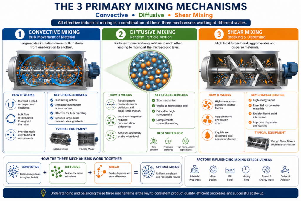
All industrial mixing processes are governed by three fundamental mechanisms:

  • Convective Mixing (Macroscopic transport)
  • Diffusive Mixing (Microscopic randomization)
  • Shear Mixing (High-energy dispersion)
The effectiveness of a mixing system depends on how well these mechanisms are generated, controlled, and balanced.


Fundamentals of Powder Mixing

Powder mixing is governed by particle mechanics and statistical distribution rather than fluid dynamics.

Key Forces Acting on Particles:

  • Gravitational forces
  • Inter-particle friction and cohesion
  • Van der Waals forces (for fine powders)
  • Electrostatic interactions
  • External mechanical forces (from mixer geometry)
Mixing vs Segregation 
 

Powder systems are inherently unstable due to segregation tendencies, driven by:

  • Particle size differences
  • Density variation
  • Shape irregularities.

Segregation mechanisms include:

  • Percolation (fine particles settling)
  • Trajectory segregation (coarse particles rolling outward)
  • Fluidization effects
Net mixing efficiency = Mixing rate – Segregation rate


Convective Mixing: Macroscopic Bulk Transport

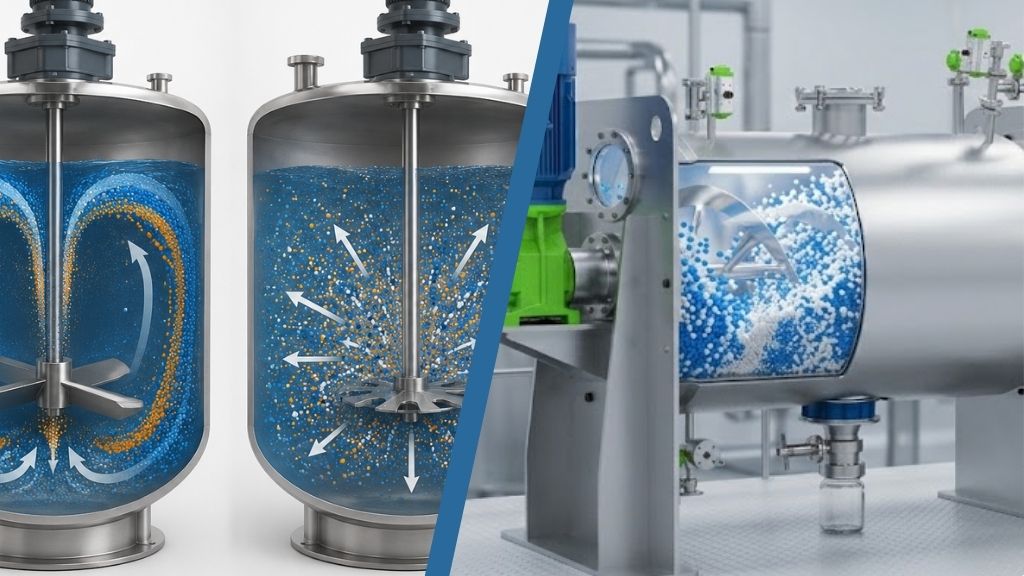
Convective mixing is the dominant mechanism in most industrial mixers and is responsible for bulk material circulation.

Mechanism:

Material is transported through the mixer via mechanically induced flow patterns, typically axial and radial.

Governing Factors:

  • Impeller geometry (ribbon, paddle)
  • Rotational speed
  • Fill level
  • Vessel geometry

Technical Insight:

Convective mixing reduces concentration gradients at macro scale, but does not ensure micro-level uniformity.

Industrial Relevance:

  • Batch blending of powders and granules
  • Pre-mixing stage before high-shear processing

Limitations:

  • Ineffective for cohesive powders
  • Cannot break agglomerates


Diffusive Mixing: Microscopic Randomization

Diffusive mixing operates at the particle level and is driven by random motion and inter-particle interactions.

Mechanism:

  • Particle collisions
  • Local rearrangement
  • Short-range movement
Mathematical Perspective:

Diffusive mixing can be described using Fickian diffusion analogies, where mixing reduces concentration variance over time.

Key Characteristics:

  • Slow compared to convective mixing
  • Critical for achieving high homogeneity
  • Strongly dependent on residence time

Industrial Importance:

  • Final stage of mixing
  • Essential in pharmaceutical and fine chemical applications

Limitation:

  • Inefficient as a standalone mechanism


Shear Mixing: High-Energy Dispersion

Shear mixing introduces localized zones of high velocity gradients, generating intense forces.

Mechanism:

  • Particle clusters are subjected to stress
  • Agglomerates are broken
  • Liquids are atomized and distributed
Governing Parameter:

  • Shear rate 
  • Power input per unit volume (P/V)

Applications:

  • Cohesive powder mixing
  • Liquid-solid blending
  • Coating and granulation

Industrial Equipment:

  • Plough shear mixers
  • High-speed dispersers

Key Advantage:

Enables deagglomeration and uniform coating, which cannot be achieved by convective or diffusive mechanisms alone.

Mixing Mechanisms


Liquid-Solid Mixing: Multiphase Complexity

Liquid-solid mixing introduces additional complexities due to phase interaction.

Key Objectives:

  • Uniform liquid distribution
  • Controlled wetting
  • Prevention of lump formation

Challenges:

  • Capillary forces leading to agglomeration
  • Non-uniform wetting
  • Localized over-saturation

Mechanism Contribution:

  • Convective Mixing → Bulk distribution of liquid
  • Shear Mixing → Breaks wet lumps and disperses liquid
  • Diffusive Mixing → Ensures micro-level uniformity

Engineering Considerations:

  • Spray nozzle design
  • Liquid addition rate
  • Droplet size distribution
  • Synchronization with mixing intensity


Homogeneity Principles and Mixing Quality

Mixing quality is quantitatively defined using statistical measures of variance.

Degree of Mixing (M):

Defined as the reduction in concentration variance:

  • • M → 0 (completely segregated)
  • • M → 1 (perfectly mixed)

Key Influencing Parameters:

  • Mixing time
  • Equipment design
  • Fill level
  • Material properties
  • Sequence of ingredient addition

Practical Reality:

Perfect mixing is unattainable – industrial processes aim for acceptable homogeneity within defined tolerance limits.

Sampling Considerations:

  • Representative sampling is critical
  • Sampling errors can misrepresent mixing quality


Scale-Up Considerations in Industrial Mixing

Scaling up a mixing process is not linear – it requires engineering equivalence between scales.

Common Scale-Up Challenges:

  • Change in flow regimes
  • Reduced mixing intensity
  • Variation in shear distribution
  • Altered residence time

Critical Scale-Up Parameters

1. Power per Unit Volume (P/V): Ensures equivalent energy input

2. Froude Number (Fr): Governs flow behavior in gravity-driven systems

3. Geometric Similarity: Maintains consistent flow patterns

4. Tip Speed / Shear Rate: Critical for dispersion and deagglomeration

Best Practice:

Scale-up should be based on dimensionless analysis and pilot validation, not simple geometric scaling.


Integrating Mixing Mechanisms for Optimal Design

In industrial systems, effective mixing is achieved by combining mechanisms:

  • Convective → Rapid bulk distribution
  • Diffusive → Micro-level uniformity
  • Shear → Agglomerate breakdown and dispersion

The design challenge lies in balancing these mechanisms based on:

  • Material characteristics
  • Process objectives
  • Product quality requirements


Final Thought: Engineering Mixing, Not Just Equipment


Industrial mixing is not a function of equipment selection alone – it is the result of applied process engineering principles.

Understanding mixing mechanisms enables:
 
  • Predictable process performance
  • Reduced trial-and-error
  • Improved scale-up success
  • Consistent product quality
Because ultimately,
mixing efficiency is not achieved by motion alone – but by mastering the physics behind it.
 

How to Select the Right Industrial Mixer for Your Process

How to Select the Right Industrial Mixer for Your Process

In most industrial plants, mixing is treated as a simple unit operation – something that happens between material handling and downstream processing. But in reality, mixing is often the single most influential factor in determining product quality, batch consistency, and overall process efficiency.

Yet, mixer selection is still commonly driven by equipment specifications – RPM, motor power, or vendor preference – rather than the process requirements themselves.

This approach leads to a familiar set of problems: inconsistent batches, long mixing times, product degradation, and costly rework.

The truth is straightforward:

You don’t select a mixer – you engineer a mixing process.

 
industrial mixer


1. Start With the Process Objective, Not the Equipment

Before evaluating any mixer type, the first question must be: What exactly are you trying to achieve through mixing?

Different objectives demand fundamentally different mixing mechanisms:

  • Homogenization → Uniform composition across the batch
  • Blending → Even distribution of multiple components
  • Dispersion → Breaking agglomerates into finer particles
  • Coating → Applying liquid onto solid particles
  • Heat Transfer → Heating or cooling during mixing
Each objective requires a specific combination of:
 
  • Shear intensity
  • Flow pattern
  • Residence time
A mismatch here is the root cause of most mixing failures.
 

However, modern manufacturing demands:

  • Repeatability 
  • Clean operations 
  • Data-driven control 
  • Operator safety  

This shift is driving the adoption of automated material handling solutions, transforming the “bag-to-process” step into a controlled, integrated, and intelligent operation.


2. Understand Material Behavior - Not Just Material Properties

Datasheets provide parameters like bulk density or particle size—but real-world mixing depends on how materials behave dynamically.

Key questions to evaluate:

  • Are the materials cohesive, free-flowing, or sticky?
  • Is there a wide variation in particle size distribution?
  • Are components prone to segregation?
  • Does the material exhibit shear sensitivity or degradation?
For example:
 
  • Fine powders may form agglomerates requiring higher shear.
  • Fragile particles (like polymer granules) may degrade under excessive mixing intensity.
  • Density differences can cause segregation even after achieving initial homogeneity.
Material behavior defines the mixing strategy.
.


3. Define the Required Degree of Homogeneity

Not all processes require the same level of mixing precision.

A critical—but often overlooked—parameter is:

“How uniform is uniform enough?”

  • Commodity products may tolerate ±5–10% variation
  • Specialty chemicals or food products may require <1% deviation
Higher precision demands: 
 
  • Better flow control
  • Optimized mixing geometry
  • Longer or more controlled mixing cycles

 Overdesigning for unnecessary precision increases CAPEX and OPEX – while underdesigning compromises quality.


4. Evaluate Batch Size, Throughput, and Flexibility

Mixer selection must align with production realities:

  • Minimum and maximum batch size
  • Production rate (TPH or batches/day)
  • Frequency of product changeovers
  • Ease of cleaning for batch changeover
Key trade-offs:
 
  • Large mixers improve throughput but reduce flexibility
  • Smaller systems improve control but may limit scalability
  • Complex mixers are often difficult to clean
In multi-product plants, flexibility often outweighs peak capacity.


5. Mixing Time vs Energy Consumption: Finding the Balance

A common misconception is that faster mixing always improves productivity.

In reality:

  • Excessive mixing can lead to product degradation
  • High energy input increases operating costs
  • Overmixing may cause segregation in powders
The goal is not maximum intensity – but optimal mixing efficiency:
 
Achieving the required homogeneity in the shortest possible time with minimal energy input.


6. Consider Process Integration, Not Standalone Equipment

A mixer does not operate in isolation. Its performance depends heavily on upstream and downstream systems:

  • Feeding accuracy (loss-in-weight, batching systems)
  • Type of conveying systems upstream & downstream
  • Discharge mechanisms
  • Automation and recipe control

Poor integration often leads to:

  • Inconsistent feed rates
  • Uneven loading
  • Extended cycle times
  • Segregation post mixing

 The most effective mixing systems are designed as part of a fully integrated process line.


7. Address Cleaning, Maintenance, and Changeover

In industries like food, chemicals, and specialty materials, cleaning is not a secondary concern – it is a critical design parameter.

Evaluate:

  • Ease of cleaning (manual or CIP)
  • Dead zones or material hold-up areas
  • Accessibility for maintenance
  • Time required for product changeover

A mixer that performs well but requires long cleaning cycles will reduce overall plant productivity.


8. Plan for Scale-Up From Day One

One of the most common industry mistakes is assuming that a mixer that works in the lab will perform the same at production scale.

In reality, scale-up introduces challenges such as:

  • Different flow patterns
  • Variations in power per unit volume
  • Changes in residence time distribution

Successful scale-up requires:

  • Geometric consistency
  • Process validation
  • Engineering expertise – not trial and error


9. Don’t Ignore Automation and Control

Modern mixing is no longer just mechanical – it is increasingly digital.

Advanced systems now incorporate:

  • PLC-based recipe control
  • Real-time monitoring
  • Batch traceability
  • Integration with plant-wide automation

Automation ensures:

  • Repeatability
  • Reduced operator dependency
  • Consistent product quality


10. The Right Mixer Is the Outcome - Not the Starting Point

Ultimately, selecting the right industrial mixer is not about choosing between designs – it is about engineering the right process conditions.

The correct approach is:

  1. Define process objectives

  2. Understand material behavior

  3. Establish quality requirements

  4. Evaluate operational constraints

  5. Design for integration and scalability

  6. Conduct trials and validate claims

Only then does the mixer type become clear.


Selection of Mixer – A Practical Decision Framework

selection of mixer

Once the process foundation is established, the final mixer selection can be made using a structured engineering approach:

Step 1: Match Process Objective to Mixer Type

Align the mixing requirement with the appropriate mechanism:

  • Blending applications → Ribbon or Paddle mixers
  • High-intensity mixing / dispersion → Plough Shear mixers
  • Gentle handling of fragile materials → Paddle mixers (Horizontal or Vertical)

This ensures the selected mixer delivers the required flow dynamics and shear profile.

Step 2: Align Material Behavior

Material characteristics refine the selection:

  • Cohesive or agglomerated powders → Plough Shear mixers for intensive mixing
  • Free-flowing materials → Ribbon mixers for efficient bulk blending
  • Fragile or shear-sensitive materials → Paddle mixers for controlled, low-impact mixing

Correct alignment prevents issues such as segregation, degradation, or inefficient mixing.

Step 3: Define Batch Size and Plant Constraints

Operational realities play a critical role:

  • Large batch sizes / high throughput → Horizontal Process Mixers
  • Space constraints / flexible operations → Vertical Process Mixers

This step ensures the mixer fits both production demand and plant layout.

Step 4: Identify Process Enhancement Requirements

Modern mixing systems often require additional process capabilities:

  • Heating or cooling requirements → Jacketed mixers
  • Liquid addition / coating applications → Integrated liquid injection systems
  • Hygiene-critical or multi-product plants → CIP (Clean-In-Place) systems
  • High accuracy and repeatability → Load cell-based weighing systems

These features transform the mixer into a controlled and repeatable process unit, rather than just a mechanical device.

Step 5: Evaluate Integration and Automation

Finally, ensure seamless integration with the overall process:

  • Feeding systems (loss-in-weight, batching)
  • Pneumatic or mechanical conveying
  • Discharge mechanisms
  • PLC-based automation and recipe control

A well-integrated mixer ensures:

  • Consistent batch quality
  • Reduced operator dependency
  • Improved overall plant efficiency


Final Thought: Shift From Equipment Selection to Process Engineering


The most successful plants don’t ask: “Which mixer should we buy?”

They ask: “What process conditions are required to achieve consistent, scalable results?”

This shift – from equipment-centric thinking to process-centric engineering – is what separates average operations from high-performance manufacturing systems.

Because in the end,

mixing is not about motion or emotion – it’s about precision, consistency, and control.


Engineering the Bag-to-Process Journey in Automated Material Handling Systems

Engineering the Bag-to-Process Journey in Automated Material Handling Systems

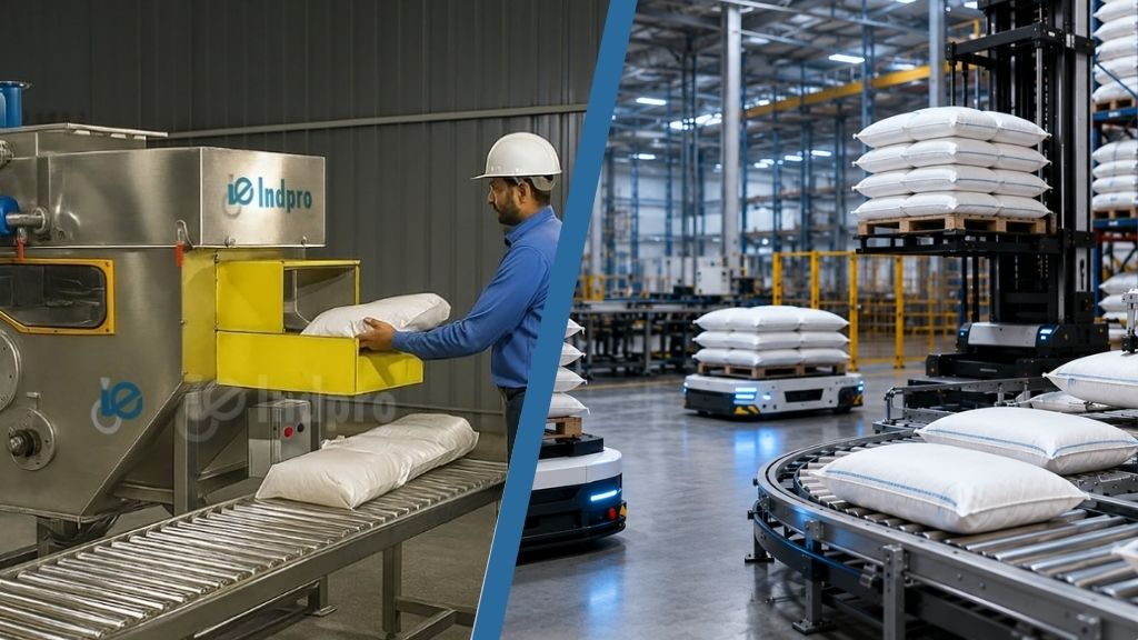
In modern manufacturing environments, substantial capital investments are directed toward high-performance process equipment such as reactors, extruders, mixers, and automated packaging lines. However, a critical yet often overlooked interface lies upstream – the transition of bulk materials from bag to process. This stage, commonly referred to as bag unloading and material feeding, plays a decisive role in overall process efficiency and product quality.

Despite its apparent simplicity, the operation of emptying bags and transferring material into downstream systems has traditionally relied on manual intervention. This introduces multiple inefficiencies, including inconsistent discharge rates, uncontrolled dust generation, and variability in material flow. More importantly, it becomes a key point where process variability is introduced – through contamination risks, material spillage and losses, operator-dependent performance, and fluctuating feed rates that directly impact downstream equipment such as feeders, mixers, and reactors.

As industries increasingly adopt automated material handling systems, with a focus on process reliability, traceability, and Industry 4.0 integration, the “bag-to-process” stage is evolving from a manual utility function into a strategic control point.

In this blog, you will gain a comprehensive understanding of how an integrated “bag-to-process” system is engineered – from bag unloading and conveying to storage, flow conditioning, feeding, and mixing – and how each stage contributes to achieve reliable, efficient, and high-quality manufacturing operations.


The Shift: From Manual Dependency to Intelligent Systems

Shift From Manual Dependency to Intelligent Systems

Traditional bag handling relied heavily on operator skill:

  • Manual bag cutting and dumping 
  • Inconsistent material discharge 
  • Dust generation and product loss 
  • Limited control over feed rate and batch accuracy  

However, modern manufacturing demands:

  • Repeatability 
  • Clean operations 
  • Data-driven control 
  • Operator safety  

This shift is driving the adoption of automated material handling solutions, transforming the “bag-to-process” step into a controlled, integrated, and intelligent operation.


Engineering the Transition: Key Elements of Automation

1. Controlled Bag Unloading Systems – For Small Bag (25 kg/ 50 kg) & Jumbo Bag

Automated bag unloading stations (automatic bag slitting machines/jumbo bag unloading stations) are no longer just dumping points – they are engineered systems designed for:

  • Dust-free operation through integrated aspiration 
  • Controlled discharge using agitation, massage paddles, or vibration 
  • Adaptability for different bag types (woven, paper, liners) 
The focus is not just on emptying the bag – but on ensuring complete, consistent, and contamination-free discharge. 
 
2. Integrated Material Transfer
 
Once discharged, the material must move seamlessly into the process. This is where pneumatic conveying systems (dense phase or dilute phase) or mechanical conveying solutions come into play.
 
Key considerations include:
 
  • Preservation of material integrity (especially for fragile or friable materials) 
  • Minimization of segregation 
  • Controlled velocity profiles to prevent degradation 
The transition from bag to pipeline is engineered to maintain material characteristics – not just to move the mass. 
 
3. Buffer Storage & Flow Conditioning Systems
 
Between conveying and processing, storage plays a far more critical role than simply “holding” material.
 
Storage Systems: 
 
  • Storage silos for bulk accumulation and process decoupling 
  • Day bins / surge hoppers for short-term, controlled feeding 
These systems act as buffers, stabilizing upstream and downstream variability.
 
Flow Discharge Mechanisms:
 
However, storage introduces a new challenge: material flow behavior.
To ensure reliable discharge, engineered solutions are essential:
 
  • Bin Activators – Induce vibration and promote mass flow 
  • Fluidized Beds / Aeration Pads – Reduce inter-particle friction for fine powders 
  • Powder Bridge Breakers – Eliminate arching and rat-holing 
This stage is where material handling transitions into bulk solids flow science, ensuring that what enters storage can be reliably extracted – every time.
 
4. Feed Control and Dosing Precision
 
The real value of automation emerges when material flow becomes measurable and controllable.
 
Technologies such as:
 
  • Loss-in-weight feeders 
  • Screw feeders with variable frequency drives 
  • Rotary airlock valves for metered discharge 
enable:
 
  • Precise dosing into downstream processes 
  • Batch consistency 
  • Integration with PLC/SCADA systems 
This transforms material handling into a quantifiable and controllable process variable.
 
5. Processing and transforming materials: From Handling to Value Creation 
 
While automated material handling ensures the reliable movement and controlled feeding of bulk solids, the true value in any manufacturing operation is realized during processing and material transformation. This is where raw materials are converted into finished or intermediate products with defined physical and chemical properties.
 
An effectively engineered “bag-to-process” system ensures that materials enter these processes in a consistent, conditioned, and controlled state, which is critical for achieving predictable and repeatable outcomes.
 
Key Industrial Processing Operations
 
v Milling and Size Reduction
 
  Milling operations are used to achieve the desired particle size distribution, which directly impacts:
 
  • Reaction kinetics 
  • Mixing efficiency 
  • Flowability and packing density 
Technologies such as hammer mills, jet mills, and ball mills rely on controlled feed rates to avoid over-grinding, heat generation, and product degradation.
 
vDrying and Moisture Control
 
  Drying processes – such as fluid bed dryers, rotary dryers, and spray dryers – are essential for:
 
  • Removing excess moisture 
  • Enhancing shelf life 
  • Improving flow characteristics 
Consistent upstream feeding ensures uniform residence time and thermal efficiency, preventing issues like over-drying or uneven moisture profiles.
 
v Mixing and Blending
 
   Mixing is a critical step in ensuring homogeneity of multi-component systems.
 
  • Horizontal mixers (Ribbon/Paddle/Plough): Ideal for rapid, high-capacity blending 
  • Vertical mixers (Ribbon/Paddle): Suitable for gentle mixing and energy-efficient operations 
Accurate dosing and controlled feeding directly influence blend uniformity, cycle time, and product consistency.
 
v Chemical Reactions and Processing
 
   In industries such as chemicals, petrochemicals, and polymers, materials undergo chemical transformations within reactors.
 
   Key dependencies on upstream handling:
 
  • Consistent feed rates for reaction stability 
  • Controlled particle size for reaction efficiency 
  • Contamination-free input for product purity
     Any fluctuation in material feeding can lead to process instability, off-spec products, or reduced yield.
 
v Heating and Cooling Operations
 
   Thermal processes are widely used for:
 
  • Phase changes 
  • Material conditioning 
  • Reaction control 
Equipment such as heat exchangers, calciners, and coolers require steady and predictable material flow to maintain thermal balance and energy efficiency.
 
v Extrusion and Forming
 
Extrusion processes are critical in polymer, food, and specialty material industries.
 
They depend heavily on:
 
  • Uniform feed composition 
  • Controlled bulk density 
  • Stable feed rates  
Variations in upstream handling can result in:
 
  • Product defects 
  • Inconsistent shapes or densities 
  • Increased rejection rates 
6. Dust Management and Environmental Compliance
 
Dust is not just a housekeeping issue – it impacts: 
 
  • Product yield 
  • Operator health 
  • Regulatory compliance  
Modern systems integrate high efficiency centralized dust extraction units. The result is a closed-loop handling environment, aligning with global safety and environmental standards.


Beyond Equipment: System Thinking

A common mistake is treating bag handling as a standalone equipment selection problem. In reality, it is a system design challenge.

Key questions include:

  • How does material behavior change from storage to discharge? 
  • What is the required feed consistency for the downstream process? 
  • How can variability be eliminated across shifts and operators? 
  • How does this integrate with plant automation architecture? 
Thought leadership in this space lies in connecting these dots, not just supplying individual components. 


Why Automation Matters?

1. Operational Efficiency: Reduced manual intervention leads to faster cycle times and higher throughput

2. Consistency and Quality: Controlled feeding ensures uniform product quality and process stability

3. Safety and Ergonomics: Eliminates repetitive manual handling, reducing workplace injuries

4. Material Savings: Minimizes spillage, dust losses, and incomplete bag discharge

5. Data and Traceability: Enables integration with Industry 4.0 systems for monitoring and optimization


Emerging Trends: The Future of Bag-to-Process Systems

Smart Material Handling: Sensors, load cells, and AI-driven analytics are enabling predictive control over material flow behavior.

 Modular System Design: Plug-and-play modules allow flexible scaling and faster deployment.

Hygienic Solutions: Driven by pharmaceutical and food industries, designs are evolving for zero contamination and high levels of hygiene. 

Containment Solutions: The need for chemical industries includes complete containment solutions for zero exposure of operators to toxic and hazardous materials.

Digital Integration: Seamless integration with MES and ERP systems is making material handling a data-rich node in the production ecosystem.


Conclusion: From Utility to Strategic Advantage

The journey from bag to process is no longer an ordinary operational step – it is a critical control point that defines process efficiency, product quality, and operational safety.

Organizations that recognize this shift are moving beyond basic handling solutions toward engineered, automated, and intelligent systems.

In doing so, they are not just improving material flow – they are unlocking a new level of process reliability and competitive advantage.